Exhaust valve

A technology of exhaust valve and exhaust hole, applied in the direction of lift valve, valve details, valve device, etc., can solve the problems of easy generation of impurities and dirt, poor exhaust performance of exhaust valve, increase of boiler and pipeline pressure, etc. Not easy to impurity and dirt, ensure normal work, improve the effect of exhaust performance

Inactive Publication Date: 2010-02-03
王旭华
View PDF1 Cites 10 Cited by
  • Summary
  • Abstract
  • Description
  • Claims
  • Application Information

AI Technical Summary

Problems solved by technology

This structure is equipped with a filter device at the slideway mouth. When there is no water in the valve body, the floating ball falls, the pores of the filter device open, and the gas is discharged from the exhaust nozzle through the valve port; when there is water in the valve body, the float rises and the filter device The pores are closed, and the impurities are blocked from the slideway, which effectively prevents impurities from entering the slideway. The disadvantages are: the thimble exhaust is used, and the thimble is prone to impurities and dirt under long-term work, resulting in poor sealing of the exhaust valve. Water leakage occurs, so that the thimble cannot move freely. There is a circular vent hole in the rubber plug of the thimble exhaust. This hole is prone to aging and hardening of the rubber plug under high temperature and long-term working conditions, resulting in exhaust The sealing performance of the air valve is poor, and the diameter of the well-known exhaust hole is 0.5-0.8mm, resulting in poor exhaust performance of the exhaust valve, resulting in an increase in the pressure of the boiler and pipeline, and poor heating effect

Method used


Image

  • Exhaust valve

Examples


Embodiment Construction

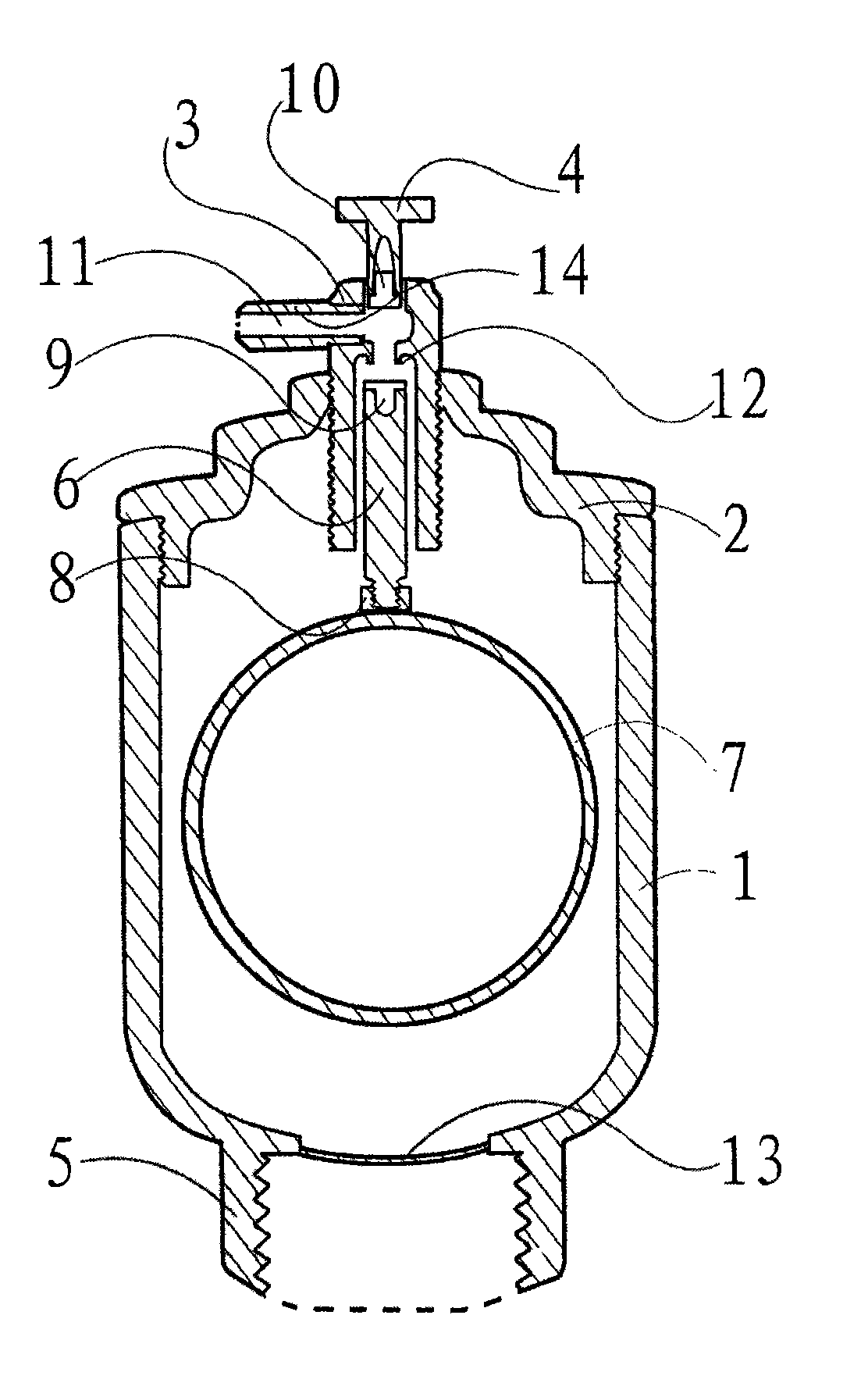
[0017] Such as figure 1 As shown, the internal thread of the upper part of the housing 1 is screwed to the external thread of the lower part of the valve cover 2. An internal threaded hole is provided in the middle of the valve cover 2 to be screwed to the valve core 3, and the valve core 3 is screwed to the exhaust nozzle 14. An exhaust hole 11 is provided inside the valve core 3 and the exhaust nozzle 14. The exhaust hole 11 at the lower end of the valve core 3 is movably installed into the floating rod 6; the exhaust hole 11 at the upper end of the valve core 3 is screwed with the manual screw 4, A silicone pad B10 is inserted into the lower part of the manual screw 4 to manually close the exhaust hole 11 to prevent the gas in the housing 1 from being discharged. An exhaust nozzle 14 is screwed on one side of the valve core 3 to discharge gas. A valve core inner port 12 is provided in the upper inner part of the exhaust hole 11 at the lower end of the valve core 3. The inn...


PUM

PropertyMeasurementUnit
diameteraaaaaaaaaa

Abstract

The invention discloses an exhaust valve which comprises inside threads arranged at the upper part of a shell, an outside thread bolt joint arranged at the lower part of a valve cover, a threaded holearranged at the middle part of the valve cover, a valve core bolt joint, a valve seat welded with the lower part of the shell, a pipeline bolt joint, a valve core and an exhaust nozzle bolt joint, wherein exhaust holes are arranged in the valve core and an exhaust nozzle, and a floating ball is arranged in the shell. The exhaust valve is characterized in that the exhaust holes arranged at the lower end of the valve core are movably installed in a floating rod, and a valve core internal opening is arranged at the inside upper part of the exhaust hole at the lower end of the valve core. The invention adopts a silicone gasket to carry out seal set and efficiently eliminates the phenomenon of water leakage generated by impurity stacking. The silicone gasket is not easy to become aging, deformand harden. For being manufactured by adopting copper materials, the valve core 3 and the valve core internal opening 12 resist high temperature and are not easy to deform, thereby greatly improvingthe exhaust performance of the exhaust valve and efficiently ensuring the normal work of a boiler and a pipeline without causing the phenomena of pressure rise, explosion and the like in the boiler and the pipeline.

Description

Technical field [0001] The invention relates to an exhaust valve, which belongs to an automatic exhaust valve device for a heating system. Background technique [0002] Known heating systems use many types of automatic exhaust valves, such as a vertical automatic exhaust valve with a thimble of Chinese patent number: 200820071822.9. The exhaust nozzle is fixed on the valve seat. There is a slideway communicating with the exhaust nozzle in the valve seat. The upper end of the slideway is the valve port. The upper end of the thimble rod on the float in the shell is in the slideway, which is characterized by the lower end of the valve seat. There is a ring groove, there is a ring groove on the thimble, and the upper and lower ends of a filter screen or slit filter device are clamped in the two ring grooves. This structure is equipped with a filter device at the chute port. When there is no water in the valve body, the float ball falls, the pores of the filter device are opened, and...

Claims


Application Information

Patent Timeline
Patent Type & Authority Applications(China)
IPC IPC(8): F16K1/00F16K1/36F16K31/22F16K27/12B01D35/04
Inventor 王旭华
Owner 王旭华
Why Eureka
Try Eureka