
Radiating structure of magnetron

A heat dissipation structure and magnetron technology, applied in the field of magnetron, can solve problems such as heat dissipation, loud noise, and product failure, and achieve the effects of increasing heat transfer efficiency, reducing working noise, and accelerating heat transfer speed

Inactive Publication Date: 2010-02-03
LG ELECTRONICS (TIANJIN) APPLIANCES CO LTD
View PDF0 Cites 2 Cited by
  • Summary
  • Abstract
  • Description
  • Claims
  • Application Information

AI Technical Summary

Problems solved by technology

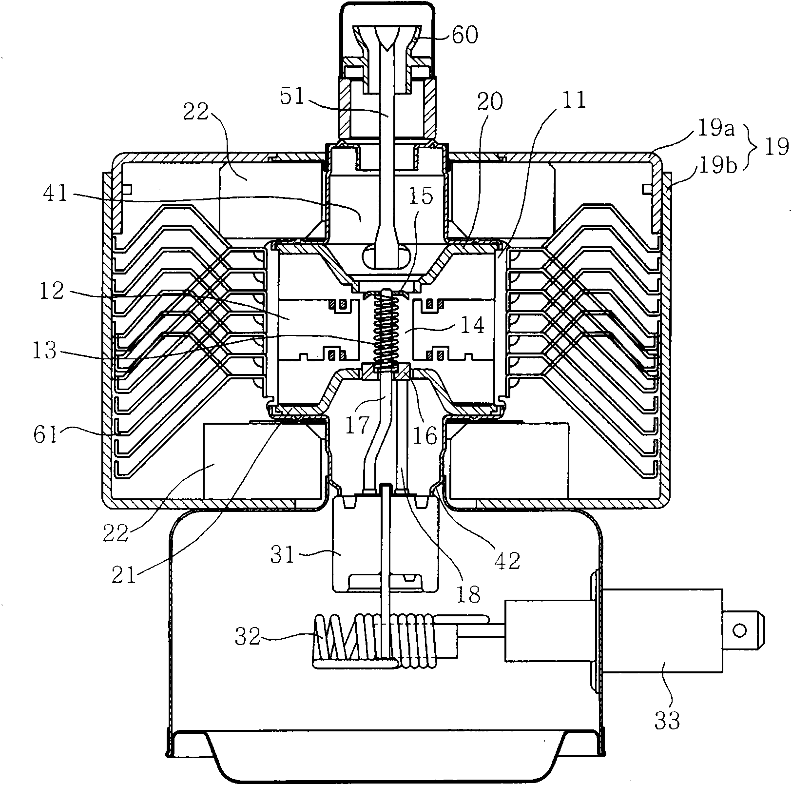
[0012] In the heat dissipation structure of the magnetron in the prior art, parallel stacked cooling fins are used for heat exchange. The heat is transmitted from the positive shell to the cooling fins through contact, and then the heat is exchanged between each cooling fin and the air flowing through the gap, so that Heat dissipation, during this process, the heat exchange efficiency between the positive shell and the heat sink is low, and the heat cannot be transferred to the heat sink in a timely manner, thus limiting the overall heat exchange capacity of the magnetron and causing the operating temperature of the magnetron to increase. Too high, easy to cause product failure
In addition, in order to improve the heat dissipation capacity of the heat sink, a high-speed fan with high air volume must be selected, which will cause excessive noise when the product is in use

Method used


Image

  • Radiating structure of magnetron
  • Radiating structure of magnetron
  • Radiating structure of magnetron

Examples


Embodiment Construction

[0027] The present invention will be described in detail below in conjunction with the accompanying drawings and embodiments.

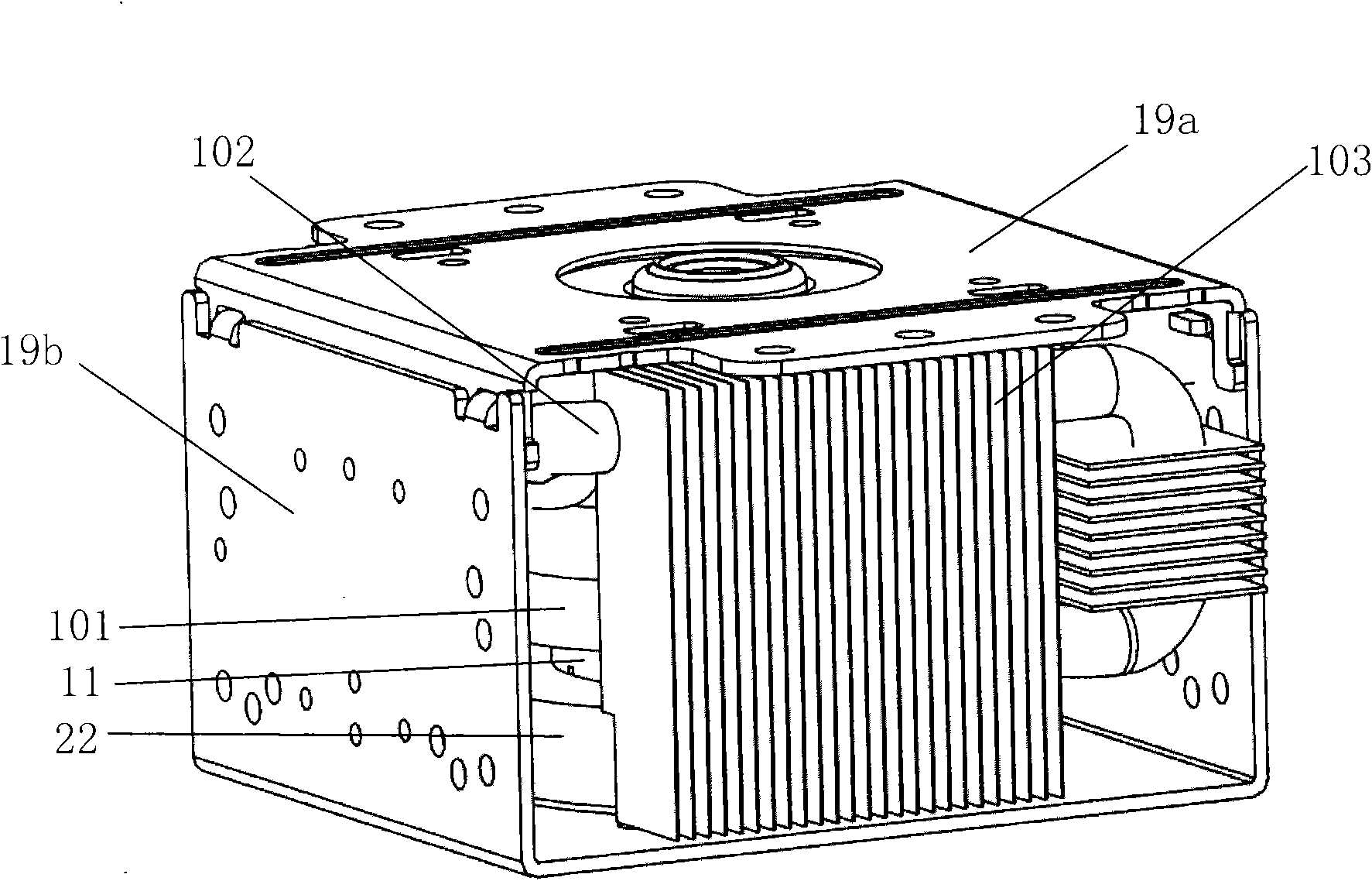
[0028] image 3 is a schematic diagram of the heat dissipation structure of the magnetron of the present invention; Figure 4 It is a schematic diagram of the back side of the heat dissipation structure of the magnetron of the present invention.

[0029] like image 3 , Figure 4 As shown, the heat dissipation structure of the magnetron of the present invention adopts a heat pipe to dissipate heat, and the diameter of the heat pipe 100 is 7 mm. In the space formed between the upper shell 19a and the lower shell 19b of the magnetron, the evaporation section 101 of the heat pipe spirals upwards and coils on the positive pole shell 11 of the magnetron, and is located between the upper and lower magnets 22. The evaporation section can be Flat tubes are used, which are tightly spiraled, and there is no gap between adjacent pipes to contact each other, ...


PUM


Abstract

The invention relates to a radiating structure of a magnetron, which adopts a heat pipe for radiating, wherein an evaporation section of the heat pipe is coiled on a positive pole shell of the magnetron in a mode of circling round upwards, a condensation section of the heat pipe is higher than the evaporation section and the positive pole shell and is spaced apart from the two for a distance, thecondensation section is provided with a plurality of radiating fins in parallel, the setting direction of the fins is consistent with the flow direction of the air flowing through the magnetron, the evaporation section and the condensation section of the heat pipe form an airtight circulation loop, and the circulation loop is filled with a working medium. The heat exchange between the heat pipe and the positive pole shell is finished through the steam-liquid phase change conversion of the working medium, the heat transfer efficiency is improved significantly, a large amount of heat can be transferred to a condensation part quickly in time, and then the condensation part performs heat exchange with the outside through the fins, so the temperature of the positive pole of the magnetron is reduced effectively. Besides, because the heat transfer efficiency of the heat pipe is improved, a fan with comparatively low rotating speed can be adopted in products so as to further reduce the workingnoises of the products.

Description

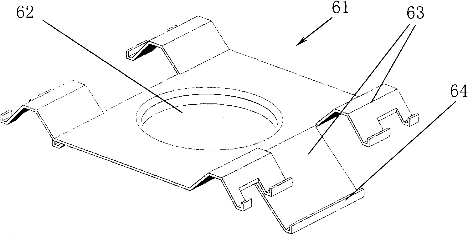
technical field [0001] The invention belongs to the technical field of magnetrons, and specifically relates to a heat dissipation structure of a magnetron in which a heat pipe is installed at the positive shell of the magnetron, and the heat pipe is used to dissipate heat to enhance heat exchange efficiency and effectively reduce the temperature of the magnetron. Background technique [0002] figure 1 It is a longitudinal sectional view of a magnetron structure in the prior art; figure 2 It is a structural schematic diagram of a magnetron heat sink in the prior art. like figure 1 , figure 2 As shown, the magnetron mainly includes: a positive electrode part; a negative electrode part; a magnetic pole part; and a microwave emitting part. The positive electrode part is composed of a barrel-shaped positive electrode case 11, and a plurality of radial blades 12 are formed on the inner wall of the positive electrode case 11, and the inner and outer rings are welded in the up...

Claims


Application Information

Patent Timeline
Patent Type & Authority Applications(China)
IPC IPC(8): H01J23/033H01J25/50
Inventor 王影
Owner LG ELECTRONICS (TIANJIN) APPLIANCES CO LTD
Learn More