Design method of intelligent power supply electronic converter of general-type railway signal lamp

A technology of railway signal lights and intelligent power supply, applied in the field of railway signal lights, can solve the problems of large influence of installation and connection distance, low conversion efficiency of power frequency transformers, and different connection methods, so as to achieve simple installation and connection and comprehensive functions. Effect

Inactive Publication Date: 2010-02-03
HOHAI UNIV CHANGZHOU
View PDF0 Cites 16 Cited by
  • Summary
  • Abstract
  • Description
  • Claims
  • Application Information

AI Technical Summary

Problems solved by technology

With the development of railway-related technologies and the continuous improvement of energy-saving and environmental protection requirements, the traditional railway signal light power supply has defects, mainly as follows: (1) The conversion efficiency of the power frequency transformer is too low, usually only 30% to 60%
(2) The power frequency transformer power supply scheme is easily affected by the instability of the grid voltage or the voltage waveform is disturbed and distorted, which seriously affects the luminous intensity and life of the signal lamp
(3) The installation and connection of the power frequency transformer power supply scheme is greatly affected by the distance, and the connection methods are different for different installation distances
(4) In the scheme of power frequency transformer power supply driving new LED railway signal lights, it is easy to cause malfunction of LED railway signal lights due to railway electrification interference

Method used


Image

  • Design method of intelligent power supply electronic converter of general-type railway signal lamp
  • Design method of intelligent power supply electronic converter of general-type railway signal lamp
  • Design method of intelligent power supply electronic converter of general-type railway signal lamp

Examples


Embodiment Construction

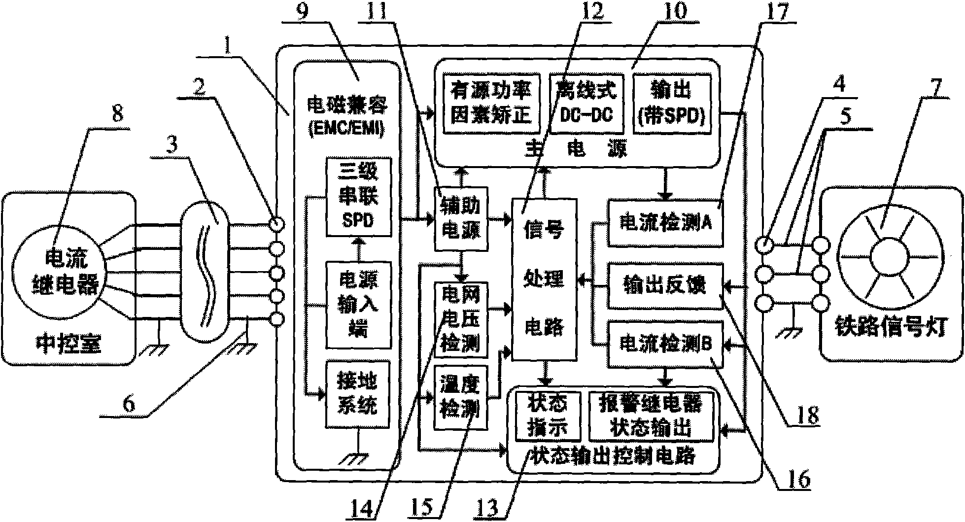
[0026] Such as figure 1 As shown, the input terminal 2 and the output terminal 4 of the power electronic converter 1 are respectively connected in series between the current relay 8 and the railway signal lamp 7 in the central control room through the shielded twisted pair cable group 3 and the twisted pair cable 5, so that There is a good connection between the power electronic converter 1 casing shielding grounding wire 6, the casing and the shielding layer of the twisted pair cable. The power electronic converter 1 includes an electromagnetic compatibility (EMC / EMI) 9 , a main power circuit 10 , an auxiliary power source 11 and a signal processing circuit 12 . Among them, the EMC 9 has a three-stage series surge protector (SPD) connected to the grounding system, the input end of the EMC 9 is connected to the current relay 8 through the shielded twisted pair cable group 3, and the output end is connected to the main power circuit 10 and the auxiliary power supply circuit 10 ...


PUM


Abstract

The invention discloses a design method of an intelligent power supply electronic converter of a general-type railway signal lamp; a converter is connected in series between a current relay in a central control room and a railway signal lamp; an electro magnetic compatibility with three-stage series surge protection function, main and auxiliary power supplies, an active power factor correction circuit, an off-line DC-DC, a signal processing circuit of which the periphery is connected with all sorts of detection circuits and a state output control circuit are connected to form the intelligent power supply electronic converter. The design method adopts surge protection, a switch power supply, a microcontroller, signal collection and processing and other technologies, and has the advantages that installation and line connection are simple, without the limitation of installation distance; the power voltage provided for the railway signal lamp is constant, the total transfer efficiency is greater than or equal to 80%; the design method specially provides a new-type LED railway signal lamp with power and the old-type railway signal lamp can be directly used by internal installation without change of the optical system of the old-type railway signal lamp.

Description

technical field [0001] The invention relates to a railway signal lamp, in particular to a power supply for driving and controlling the railway signal lamp in an intelligent manner. Background technique [0002] The traditional railway signal light power supply scheme is to input the AC power from the central control room through the AC180V or AC220V interface of the railway signal light industrial frequency power transformer, and then select the appropriate output voltage from the three outputs of AC13V, AC14V and AC16V to drive the railway signal light. With the development of railway-related technologies and the continuous improvement of energy-saving and environmental protection requirements, the traditional railway signal light power supply has defects, mainly as follows: (1) The conversion efficiency of the power frequency transformer is too low, usually only 30% to 60%. (2) The power frequency transformer power supply scheme is easily affected by the instability of the...

Claims


Application Information

Patent Timeline
Patent Type & Authority Applications(China)
IPC IPC(8): H05B37/00H05B37/02H05B37/03
CPCY02B20/48Y02B20/44Y02B20/40
Inventor 陈秉岩周娟朱昌平周国华张福章王怡顾文斌
Owner HOHAI UNIV CHANGZHOU
Why Eureka
Try Eureka