Vibrating wire sensor using spectral analysis

A spectrum, vibrating wire instrument technology, applied in the field of sensors, can solve problems such as inability to distinguish string resonance from external noise sources, errors, etc.

Active Publication Date: 2010-02-03
CAMPBELL SCI
View PDF0 Cites 12 Cited by
  • Summary
  • Abstract
  • Description
  • Claims
  • Application Information

AI Technical Summary

Problems solved by technology

Although these methods are computationally efficient, they often suffer from errors due to their inability to distinguish string resonances from extern

Method used


Image

  • Vibrating wire sensor using spectral analysis
  • Vibrating wire sensor using spectral analysis
  • Vibrating wire sensor using spectral analysis

Examples


Embodiment Construction

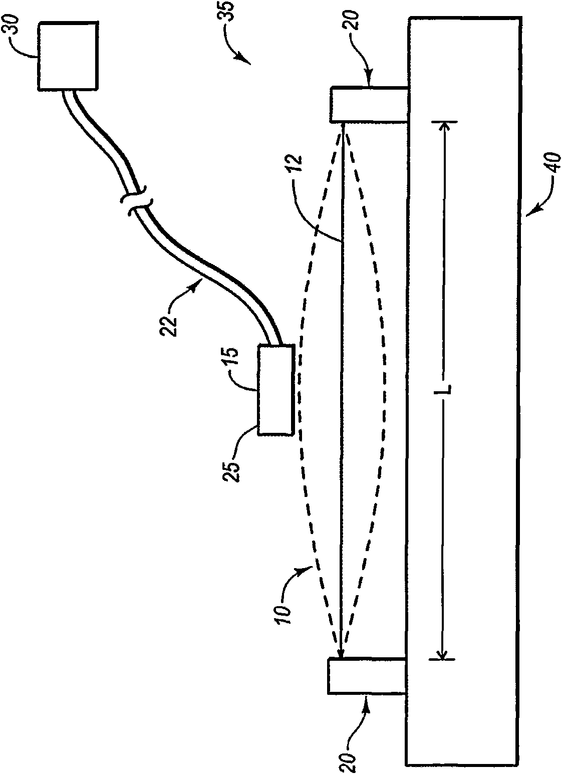
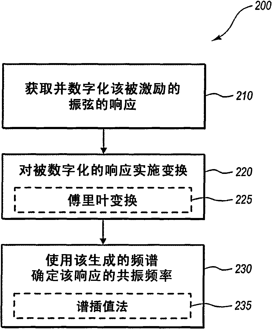
[0028] Embodiments of the invention relate to vibrating wire instruments and methods of determining the resonant frequency of the vibrating wire using spectral analysis. As briefly described above, the present invention is suitable for use in connection with vibrating wire instruments. More specifically, the invention is applicable to the conversion of raw responses collected by a vibratory gauge mechanism into digitized data, and the conversion of the digitized data into an accurate estimate of the resonant frequency of the vibrating wire. As previously mentioned, the resonant frequency of the vibrating wire can be used to calculate or estimate any number of properties, including but not limited to strain, stress, load, deflection, gas pressure, fluid pressure, displacement, liquid level, angular rotation, temperature , wind speed, fluid flow, precipitation, snow water equivalent, etc. or any combination thereof.

[0029] figure 1 A schematic diagram of one embodiment of a ...


PUM


Abstract

Systems and methods for analyzing the resonant frequency of vibratory wires within vibratory wire gauges. The resonant frequency of the vibrating wire is determined by using an interface that digitizes the response of an excited wire in the gauge. A transform then converts the digitized data into a frequency spectrum. The resulting spectrum is used to estimate the resonant frequency of the vibrating wire. The resulting measurement or estimate of the resonant frequency can be used to measure or determine some physical characteristic of the device or structure or system connected to the gauge.

Description

technical field [0001] The present invention generally relates to sensors. More specifically, embodiments of the present invention relate to vibrating wire gauges. Background technique [0002] Vibrating wire meters are used in a wide variety of applications, including measuring various properties and forces in construction projects, including buildings, bridges, dams, piles, tunnel linings, pipelines, anchorage and others. The vibrating wire instrument has been adapted to monitor stress, strain, deflection, pressure, displacement, liquid level, angular motion and temperature. Although advances in technology have produced other types of sensors, vibrating wire meters are often considered the best sensors for use in many environments due to the sensor's long-term reliability. [0003] The vibrating wire instrument generally works on the vibrating wire principle, which stipulates that when the wire is plucked, it vibrates at its resonant frequency. The resonant frequency is...

Claims


Application Information

Patent Timeline
IPC IPC(8): G01L1/10
CPCG01H13/00
Inventor 拉里·尤金·雅各布森大卫·莱尔·伊兹列尔森乔迪·艾伦·斯文森
Owner CAMPBELL SCI
Why Eureka
Try Eureka