Using method for semi-automatic frame combined welding tool

A welding tooling, semi-automatic technology, applied in welding equipment, auxiliary welding equipment, welding/cutting auxiliary equipment, etc., can solve the problems of inaccurate spatial positioning of frame welding tooling, reducing welding labor intensity, and difficulty in frame ejection. Achieve the effect of reducing welding labor intensity, simple structure and small deformation of the frame

Inactive Publication Date: 2015-11-25
LUOYANG JINUO ELECTRIC VEHICLE CO LTD
View PDF6 Cites 4 Cited by
  • Summary
  • Abstract
  • Description
  • Claims
  • Application Information

AI Technical Summary

Problems solved by technology

[0003] The purpose of the present invention is to overcome the problems of many welding points, high working intensity, and difficult spatial positioning in the overall frame welding in the prior art. Difficulty in mold release. Through reasonable design, a method of using semi-automatic frame assembly welding tool is provided. The structure is simple, the welding construction surface is conc...

Method used


Image

  • Using method for semi-automatic frame combined welding tool
  • Using method for semi-automatic frame combined welding tool

Examples


Embodiment 1

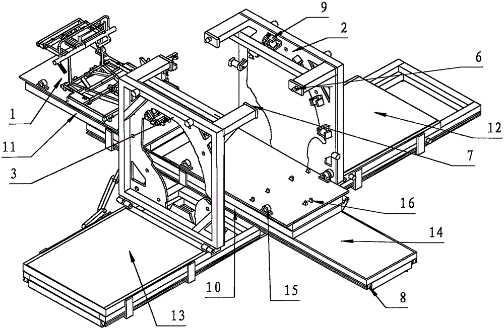
[0023] Wire gauge 8 is set under the combined welding tool of the frame, and three sections of stations are respectively set for wire gauge 8: at least one mobile station is reserved above the three sections of wire gauge 8, and at least one mobile chassis tooling is set above wire gauge 8 Component platform 1; chassis assembly welding station 11 is set in front of central assembly welding station 10, and assembly replacement station 14 is arranged behind central assembly welding station 10; horizontal guide rails are symmetrically arranged on both sides of center assembly welding station 10 section wire gauge 8; The assembly welding station 10 is arranged in a symmetrical line with the left door frame assembly welding station 12 and the right door frame assembly welding station 13;

[0024] The left door frame assembly welding station 12 on the left side of wire gauge 8 is provided above one end of the left door frame tooling assembly positioning frame 2, and the flipping devi...

Embodiment 2

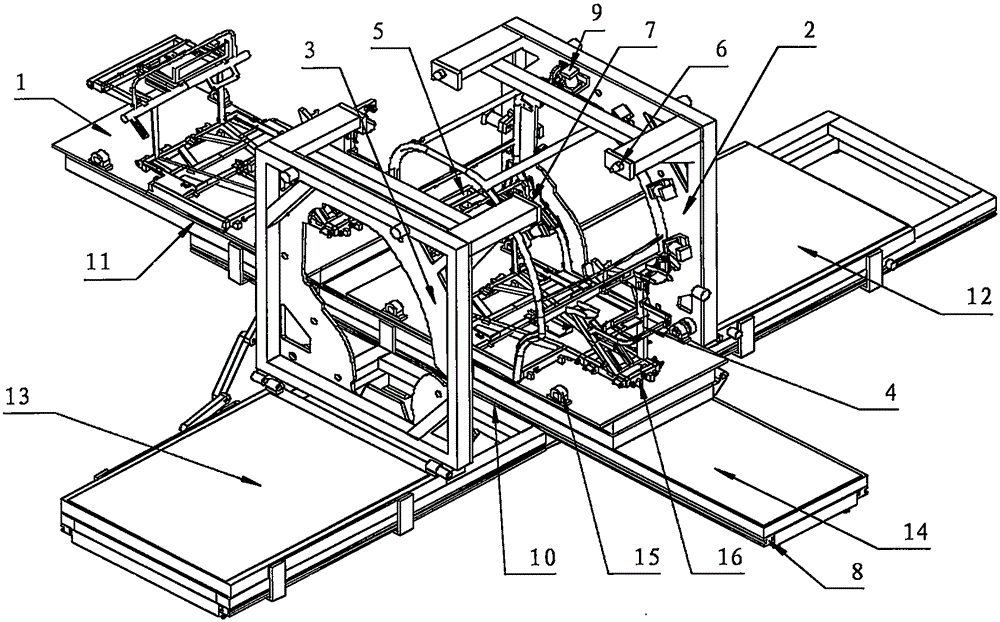
[0028] After the chassis tooling component platform 1 moves to the central assembly welding station 10, start the air pump, and place the left door frame in the bayonet of the door frame opening reserved for the left door frame tooling component positioning frame 2 to clamp the cylinder 9, open the air valve, and clamp the cylinder 9 to pass through The rod clamps the left door frame and the right door frame tooling component positioning frame 3 to reserve the door frame mouth and clamps the right door frame in the bayonet of the clamping cylinder 9, and opens the air valve, and the clamping cylinder 9 clamps the left door frame through the rod; The door frame tooling assembly positioning frame 2 and the right door frame tooling assembly positioning frame 3 are correspondingly turned over, and the left door frame and the right door frame are driven to turn over and correspond respectively.

Embodiment 3

[0030] Then, the hydraulic devices on the left side and the right side start respectively, and promote the left door frame tooling assembly positioning frame 2 and the right door frame tooling assembly positioning frame 3 to move to the central assembly welding station 10; promote the left door frame and the right door frame to the front suspension tooling assembly 4 and The beam of the rear suspension tool assembly 5 is positioned and clamped, and when the positioning pin 6 of the positioning frame is clamped with the positioning pin seat 7, the assembly welding is carried out.


PUM


Abstract

The invention discloses a using method for a semi-automatic frame assembly welding tool. The using method comprises: arranging a wire gauge below a frame combined welding tool, respectively arranging three sections of mobile stations on the wire gauge, and arranging at least one movable chassis tool assembly platform above the wire gauge; arranging a chassis assembly welding station in front of a central assembly welding station, arranging an assembly replacing station behind the central assembly welding station, and symmetrically arranging symmetrical lines of a left door frame assembly welding station and a right door frame assembly welding station at the two sides of the central assembly welding station; and during working, placing the chassis tool assembly platform into a chassis tool assembly, moving the chassis tool assembly platform to a central assembly welding station by virtue of the wire gauge and stopping the chassis tool assembly platform after assembly welding is completed, then, turning over a left door frame and a right door frame to correspond to each other respectively by virtue of a left door frame tool assembly locating rack and a right door frame tool assembly locating rack, pushing a left door frame and a right door frame to clamp by virtue of a hydraulic device, and locating a locating pin and a locating pin base of a beam to carry out assembly welding. According to the using method, the structure is simple, the welding construction surface is concentrated, the frame is precisely located and the welding is automatic.

Description

technical field [0001] The invention relates to the use of a welding tool for vehicle frame processing equipment, in particular to a method for using a semi-automatic vehicle frame combined welding tool. Background technique [0002] At present, the traditional frame is welded by a variety of components, and then the assembly welding is carried out; the welding of the overall frame has problems such as many points, high work intensity, and difficult spatial positioning. The positioning of workpieces on components and components The spatial positioning between the frames is very important to the position accuracy setting of the frame. The traditional frame welding tooling has a lot of inaccurate spatial positioning, and the difficulty of releasing the frame after assembly and welding is difficult to solve. In view of the above reasons, the existing There are a lot of inaccurate spatial positioning in the frame welding tooling, and it is difficult to release the frame after we...

Claims


Application Information

Patent Timeline
IPC IPC(8): B23K37/04B23K37/047
CPCB23K37/0435B23K37/047B23K2101/006
Inventor 秦兆华吕梦龙
Owner LUOYANG JINUO ELECTRIC VEHICLE CO LTD
Why Eureka
Try Eureka