Airway pressure relief valve

A technology of airway pressure and safety valve, applied in the direction of safety valve, valve, valve details, etc., can solve the problems of safety valve operation, easy to exceed, complicated control method, etc., to achieve the effect of smooth exhaust and safety protection

Inactive Publication Date: 2010-02-10
BEIJING AEONMED
View PDF6 Cites 19 Cited by
  • Summary
  • Abstract
  • Description
  • Claims
  • Application Information

AI Technical Summary

Problems solved by technology

At present, the control methods of airway pressure safety valve are mainly electromagnetic control and mechanical control. The safety pressure of the mechanically controlled safety valve is unstable
[0003] When the pressure in the airway reaches the opening pressure of the safety valve, the airway pressure pushes the piston 2 to move to the right through the first vent hole a ( figure 1 direction in the middle), then the safety valve is quickly opened to exhaust (that is, the head of the piston 2 leaves the first vent hole a, the gas in the air passage enters the chamber of the valve body 1 and is discharged through the second vent hole b), and the gas in the air passage The pressure drops rapidly, so that the safety valve closes quickly (that is, the piston 2 seals the first vent hole again), and at this time, the pressure in the air passage reaches or exceeds the opening pressure of the safety valve, and the safety valve opens again, and so on. , so that the pressure monitored by the ventilator system fluctuates continuously. When observing the pressure gauge, the operator will find that the pointer swings violently, and the repeated opening and closing of the mechanically controlled safety valve will also cause instantaneous high pressure in the airway of the system.
The above situation will not only make the operator's monitoring of the air pressure unchanged, but also the possible instantaneous high pressure of the system may easily exceed the range of the pressure gauge, thereby damaging the pressure gauge and causing injury to the patient

Method used


Image

  • Airway pressure relief valve
  • Airway pressure relief valve

Examples


Embodiment Construction

[0023] The specific implementation of the present invention will be described below with reference to the accompanying drawings and in conjunction with the preferred embodiments of the present invention.

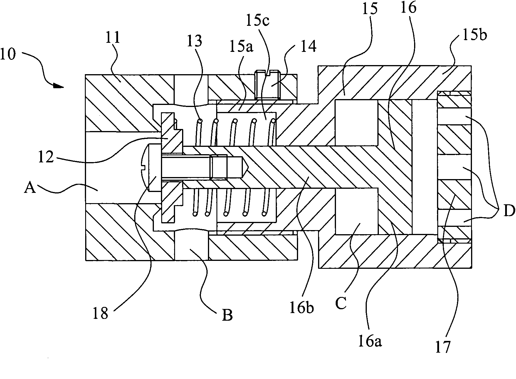
[0024] Reference figure 2 , Which shows a schematic cross-sectional structure diagram of an airway pressure safety valve according to a preferred embodiment of the present invention. The airway pressure safety valve mainly includes: a valve body 11, which has a first vent hole A communicating with the patient’s airway and a second vent hole B communicating with the atmosphere; a sealing ring (that is, the second end of the piston 16, In this case, the second end of the piston is detachable) 12, which is arranged in the chamber of the valve body 11 and abuts on the first vent hole A to seal the first vent hole A when the safety valve is not opened. Spiral spring (elastic member) 13, which is arranged in the cavity of the valve body 11 and one end biases the sealing ring 12, th...


PUM


Abstract

The invention provides an airway pressure relief valve. The valve comprises a valve body, a damping cavity connected to the valve body, a piston and an elastic piece, wherein the valve body is provided with a first vent hole communicated with an airway of a patient and a second vent hole communicated with atmospheric environment; the damping cavity is internally provided with a damping air chamber communicated with the atmosphere; the piston passes through the damping cavity, the damping air chamber is formed in a chamber of the damping cavity through a first end of the piston, and the first end can move along the chamber of the damping cavity; the second end of the piston is positioned in the chamber of the damping cavity and seals up or opens the first vent hole along with the movement of the piston; and the elastic piece is arranged in the chamber of the valve body and presses the second end of the piston eccentrically. The airway pressure relief valve adopts a mode of mechanical control, has simple structure, and can control and maintain the safety pressure of the airway steadily. When pressure reaches the opening pressure of the relief valve, the relief valve can exhaust steadily without generating obvious and vigorous pressure fluctuation.

Description

Technical field [0001] The present invention relates to a gas pressure control device, in particular to an airway pressure safety valve used in an airway system. Background technique [0002] For medical ventilation devices such as ventilators or anesthesia machines, airway pressure safety valves need to be installed to control the pressure in the patient's airway so that the pressure does not exceed the safe range. At present, the control methods of airway pressure safety valves are mainly electromagnetic control and mechanical control, both of which have corresponding shortcomings: electromagnetically controlled safety valves cannot work in an environment without power supply, and the control methods are relatively complicated; and currently commonly used The safety pressure of the mechanically controlled safety valve is unstable. figure 1 It shows a schematic cross-sectional structure diagram of an airway safety pressure valve in the prior art. As shown in the figure, the saf...

Claims


Application Information

Patent Timeline
Patent Type & Authority Applications(China)
IPC IPC(8): A61M16/20A61M39/22F16K17/04F16K47/02F16K25/00F16K27/00
Inventor 申佑方
Owner BEIJING AEONMED
Why Eureka
Try Eureka