Emergency facility glass crushing device

A technology of glass and facilities, which is applied in the field of glass crushing devices, can solve problems such as inability to use tools, low efficiency, and missed opportunities for self-rescue and rescue, and achieve the effects of small size, easy installation, and low price

Inactive Publication Date: 2010-02-10
江忠军
View PDF0 Cites 22 Cited by
  • Summary
  • Abstract
  • Description
  • Claims
  • Application Information

AI Technical Summary

Problems solved by technology

However, when sudden danger occurs in these densely populated places, people's panic often makes people feel overwhelmed and do not know how to save themselves.
Even if the above-mentioned tools are used to break the glass, the efficiency is low, and the timing of self-rescue and rescue

Method used


Image

  • Emergency facility glass crushing device
  • Emergency facility glass crushing device
  • Emergency facility glass crushing device

Examples


Embodiment 1

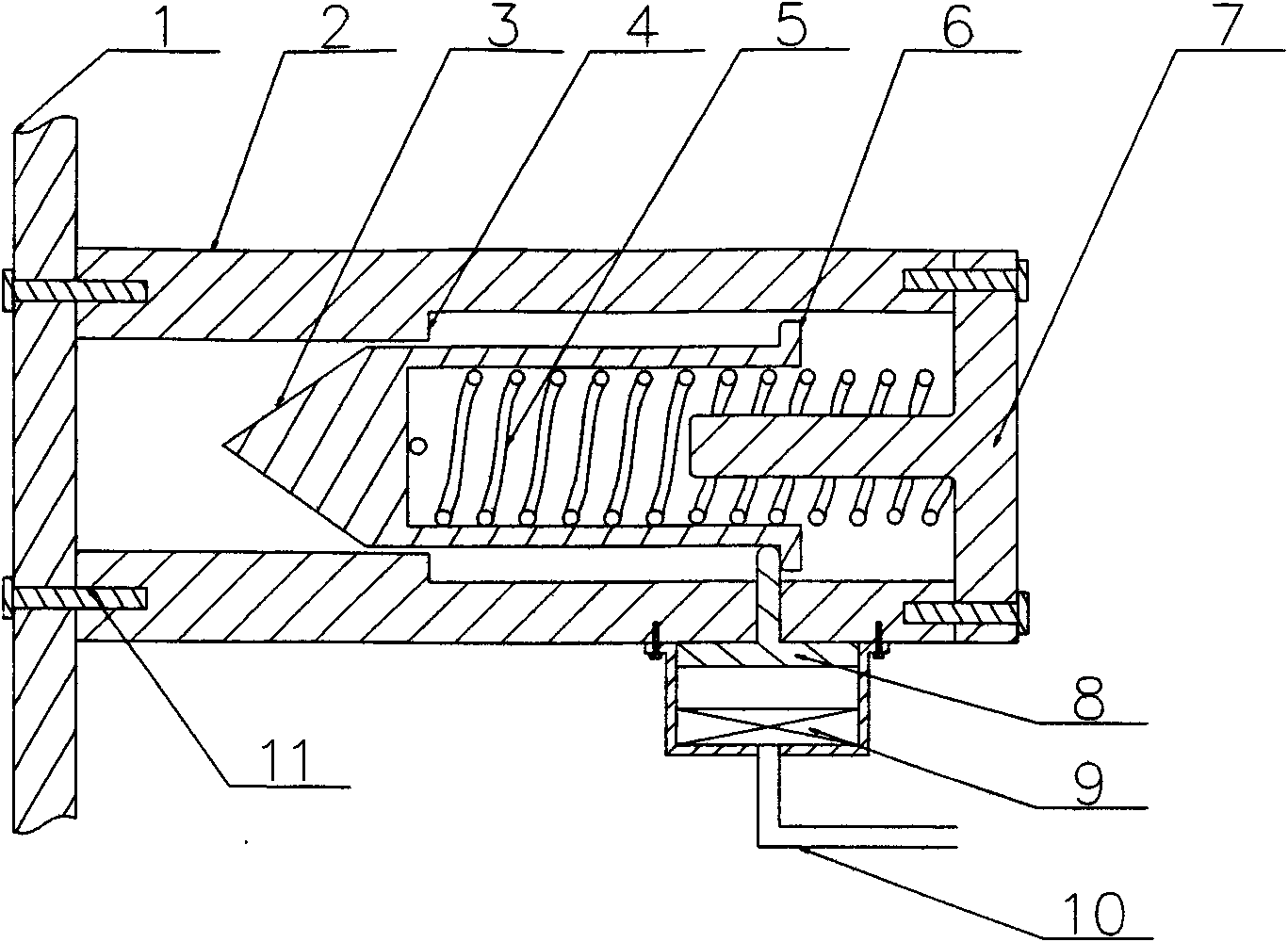
[0018] see figure 1 , is the first embodiment of the glass crushing device for emergency facilities, and is composed of the following parts: a housing 2, an end cover 7, an impact body 3, a drive device for the impact body—a spring 5 and a controller for the drive device. The controller of the driving device includes an energy release actuator—a “T”-shaped locking lever 8 and an energy release controller 9 . Described shell 2 is a hollow cylinder, is installed perpendicular to glass plane 1, and one end of shell 2 is vertically fixed on glass plane 1 with bolt 11, and the other end is connected on the end cover 7 with bolt 11. A shoulder 4 is also formed on the inner wall of the housing 2 to limit the sliding of the impact body to the glass plane 1 . The impact body 3 is installed inside the casing 2 and axially slides and fits with the inner wall of the casing 2 . The front end of the impact body 3 is a solid cone corresponding to the glass plane 1; the rear end is a hollow...

Embodiment approach

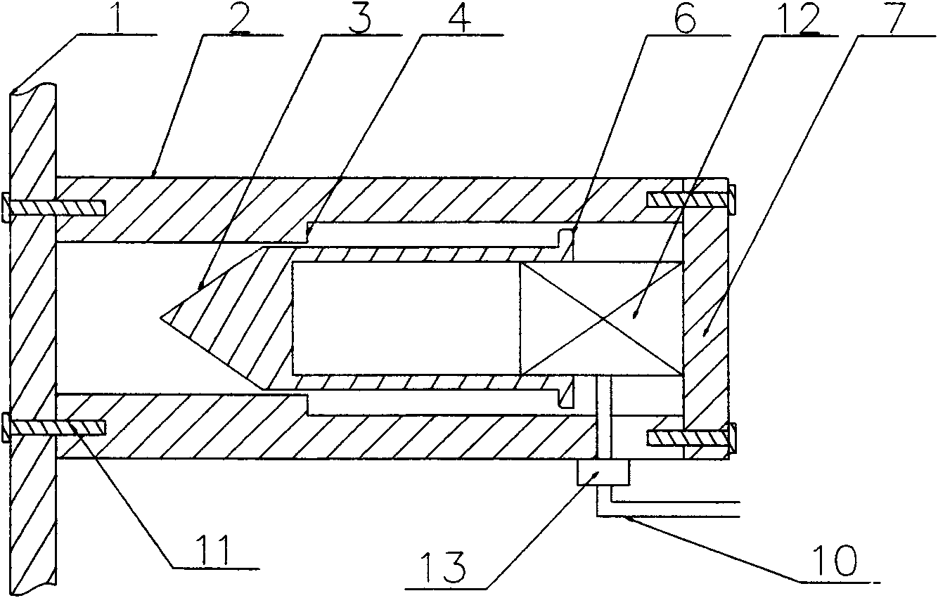
[0021] see figure 2 , is the second embodiment of the emergency facility glass smashing device, which is composed of the following parts: a housing 2, an impact body 3, a drive device 12 for chemical energy storage, and an electronic switch 13. The housing 2 is perpendicular to the glass plane 1 , and one end of the housing 2 is vertically fixed on the glass plane 1 with a bolt 11 , and the other end is connected to the end cover 7 with a bolt 11 . The inner wall of the shell body 2 is also formed with a shoulder 4 that limits the sliding of the impact body to the glass plane 1 . The impact body 3 is installed in the center of the housing 2 and axially slidably fits with the inner wall of the housing 2 . The front end of the impact body 3 is a solid cone corresponding to the glass plane 1; the rear end is a hollow cylinder. A collar extends from the bottom of the hollow cylinder at the rear end of the impact body 3 toward the inner wall of the housing 2 , corresponding to t...


PUM


Abstract

The invention discloses an emergency facility glass crushing device comprising a housing, an end cover, an impact body, a driving device of the impact body and a controller of the driving device, wherein, one end of the housing is vertically fixed on the glass plane, and the other end is fixed with the end cover; the impact body is arranged in the housing and is in axial slide fit with an inner wall shaft in the housing; the driving device is arranged on the end cover and is a mechanical energy storage or chemical energy storage driving device; the controller of the driving device is connectedwith a manual control switch and an inductive switch. When emergency occurs, under the condition that people send out orders or the sensing control judges that glass needs to be crushed, the device of the invention can quickly, automatically, efficiently and safely crush glass doors and windows, so that people can run away from sealed environment or take out sealed objects. The device of the invention has simple structure, small volume, low cost and convenient installation, can be widely applied to environment adopting glass windows and doors, such as transportation facilities, building windows and doors, emergency kits and the like.

Description

technical field [0001] The invention discloses a glass crushing device for emergency facilities, which belongs to the field of lifesaving and fire emergency devices. Background technique [0002] In densely populated vehicles, public places and other places, once an emergency occurs, people often come to emergency and escape by setting safety doors in advance, smashing glass doors, windows and taking out emergency equipment enclosed in glass doors. Glass doors, windows and emergency boxes in these places are generally equipped with tools for manually breaking glass such as axes and hammers. For example, hammers and hammers are generally installed on the side of some windows on the bus; axes are generally installed next to the fire emergency box. However, when sudden danger occurs in these densely populated places, people's panic often makes people feel overwhelmed and do not know how to save themselves. Even if the above-mentioned tools are used to break the glass, the eff...

Claims


Application Information

Patent Timeline
IPC IPC(8): A62B99/00B60R21/02
Inventor 江忠军
Owner 江忠军
Why Eureka
Try Eureka