

Cascading type rectifier used for SCR denitration device
A rectifier and stacked technology, which is applied in the field of flue gas purification, can solve the problems of insufficient cost savings and achieve the effects of material saving, overall weight reduction and easy replacement
- Summary
- Abstract
- Description
- Claims
- Application Information
AI Technical Summary
Problems solved by technology
Method used
Image

Examples
Embodiment 1
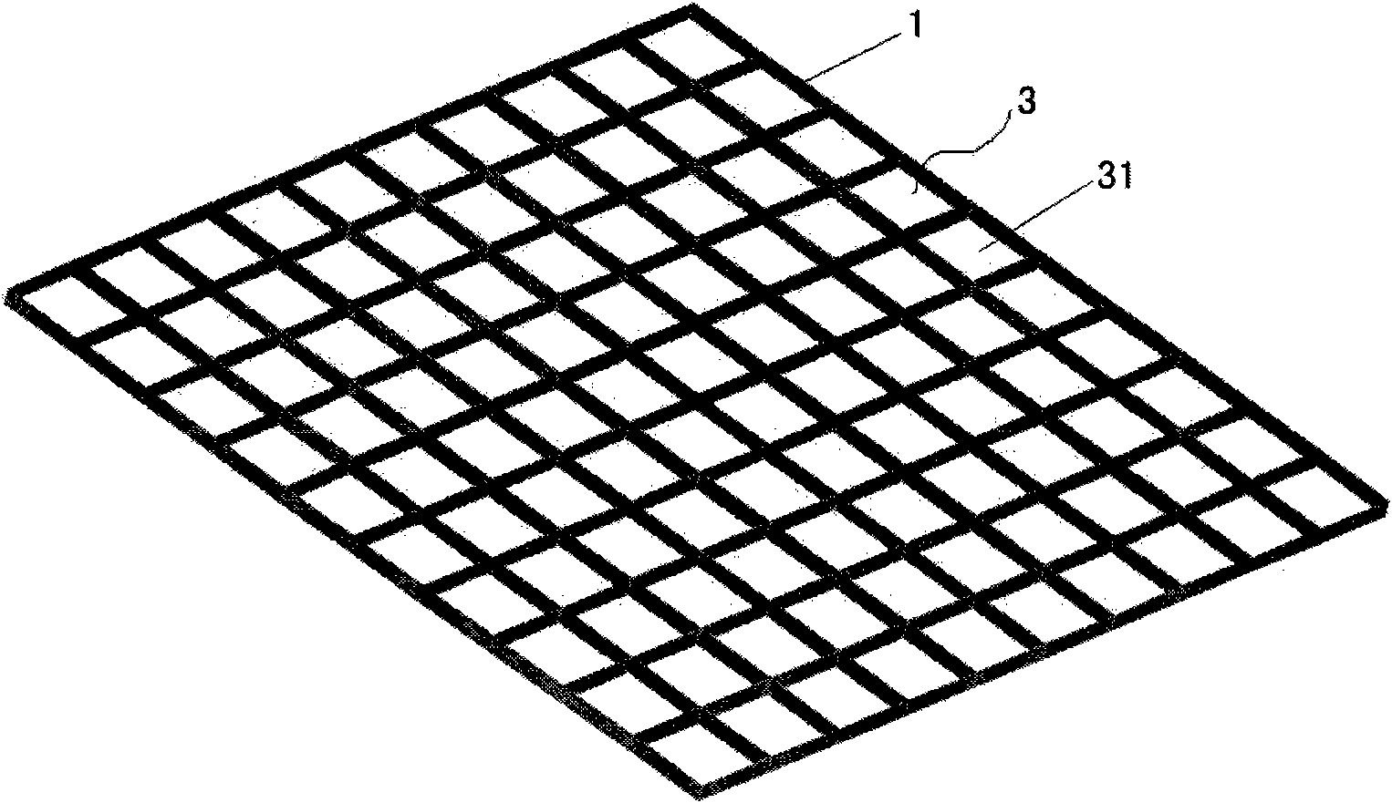
[0031] The stacked rectifier used for SCR denitrification equipment of the present invention includes an upper rectifying plate 1 and a lower rectifying plate 2 stacked together, and the upper rectifying plate 1 is provided with several regularly arranged rectifying holes 1 passing through the body of the upper rectifying plate 3. The lower rectification plate 2 is provided with a rectification hole II 4 corresponding to the rectification hole I 3 and passing through the body of the lower rectification plate. The rectification hole I 3 and the rectification hole II 4 partially overlap in the vertical direction, and the overlapping parts form multiple The rectification passage vertically runs through the rectifier body. In this embodiment, the upper rectification plate 1 and the lower rectification plate 2 have the same area and the same size, and they are all rectangular plates;
[0032] Such as figure 2 As shown, the rectification hole I 3 includes a plurality of square hole...
Embodiment 2
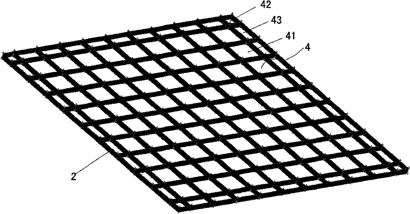
[0037] In this embodiment, the upper rectifying plate 1 and the lower rectifying plate 2 are still rectangles with the same area and overlapping four sides when stacked, and are formed by vertical and horizontal arrangement of steel bars with a thickness of less than 1 cm and welded as a whole. Figure 5 As shown, the upper rectifying plate 1 adopts a sieve-like structure, and the whole of the upper rectifying plate 1 is evenly divided into a plurality of rectifying holes I3 by steel bars. It can be seen from the figure that the rectifying holes I3 are rectangular holes, and the specifications of the rectifying holes I3 have two types. Kind, wherein the width of the rectifying hole I3 arranged at the two ends of the lower rectifying plate 2 is smaller than the rectifying hole I3 arranged in the middle of the lower rectifying plate 2, in this embodiment, the width of the rectifying hole I3 at both ends is approximately equal to the rectifying hole I3 in the middle half of the wi...
Embodiment 3
[0039] Such as Figure 8As shown (the solid line small box in the figure represents the rectification hole I, the dotted line small box represents the rectification hole II, and the shaded part represents the rectification channel), the difference between embodiment two and the implementation one is that the rectification hole I3 and the rectification hole The hole II 4 is arranged obliquely, wherein, along the same direction of the horizontal plane, the rectification hole I 3 is set at a left inclination of 45°, the rectification hole II 4 is set at a right inclination of 45°, and any two rectification holes I 3 on the upper rectification plate The two rectification holes II 4 corresponding to the lower rectification plate are overlapped at both ends in the vertical direction, correspondingly forming four rhombus rectification channels.
PUM
| Property | Measurement | Unit |
|---|---|---|
| Thickness | aaaaa | aaaaa |
Abstract
Description
Claims
Application Information