
Method for monitoring construction of channel bridge demolition

A construction monitoring and bridge technology, applied in building maintenance, special data processing applications, instruments, etc., can solve problems such as difficulty in accurate finite element simulation analysis, difficulty in strength and stability, and lack of special specifications and technical standards, and achieve perfection. The effect of bridge demolition technology, reducing safety risk and improving construction level

Inactive Publication Date: 2010-02-10
JIANGSU TRANSPORTATION RES INST CO LTD
View PDF0 Cites 21 Cited by
  • Summary
  • Abstract
  • Description
  • Claims
  • Application Information

AI Technical Summary

Problems solved by technology

[0005] (2) At present, there are no special norms and technical standards for bridge demolition construction, especially for the lack of unified process standards for the demolition of channel bridges. Navigation requirements, efficient monitoring and control during the construction process is necessary;
[0006] (3) During the demolition process of the bridge, the demolition of components will lead to changes in the structural system, and the overall and local stress state and mechanical performance of the structure will also change. Therefore, it is a difficult problem to ensure the strength and stability of the structure during the demolition construction process ;
[0007] (4) The structure to be demolished usually has a certain amount of cumulative damage before and during the demolition process, which brings certain difficulties to the accurate finite element simulation analysis, and it is difficult to determine the real stress state of the structure;

Method used


Image

  • Method for monitoring construction of channel bridge demolition
  • Method for monitoring construction of channel bridge demolition

Examples


Embodiment 1

[0023] A certain bridge was built in the late 1980s. It spans a third-class waterway. The main span is a 94.4-meter oblique-leg solid-end girder. The abutment is a frame structure supported on piles and soil foundations. As a structure, the main bridge is composed of double-width and double-chamber box girders, and the two box girders are connected by 50cm-wide longitudinal post-cast concrete.

[0024] Considering the actual operation status of the bridge and the widening and reconstruction of urban roads, the bridge was demolished and rebuilt. In order to ensure the quality and safety of the bridge demolition process, a monitoring and early warning system was established during the bridge demolition process, and a monitoring method for channel bridge demolition and construction was implemented.

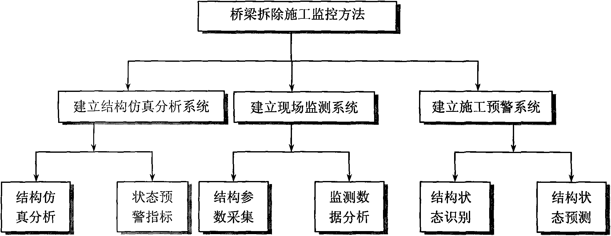
[0025] like figure 1 As shown, the channel bridge demolition construction monitoring method includes the following steps:

[0026] Step (1) Bridge demolition process

[0027] First...


PUM


Abstract

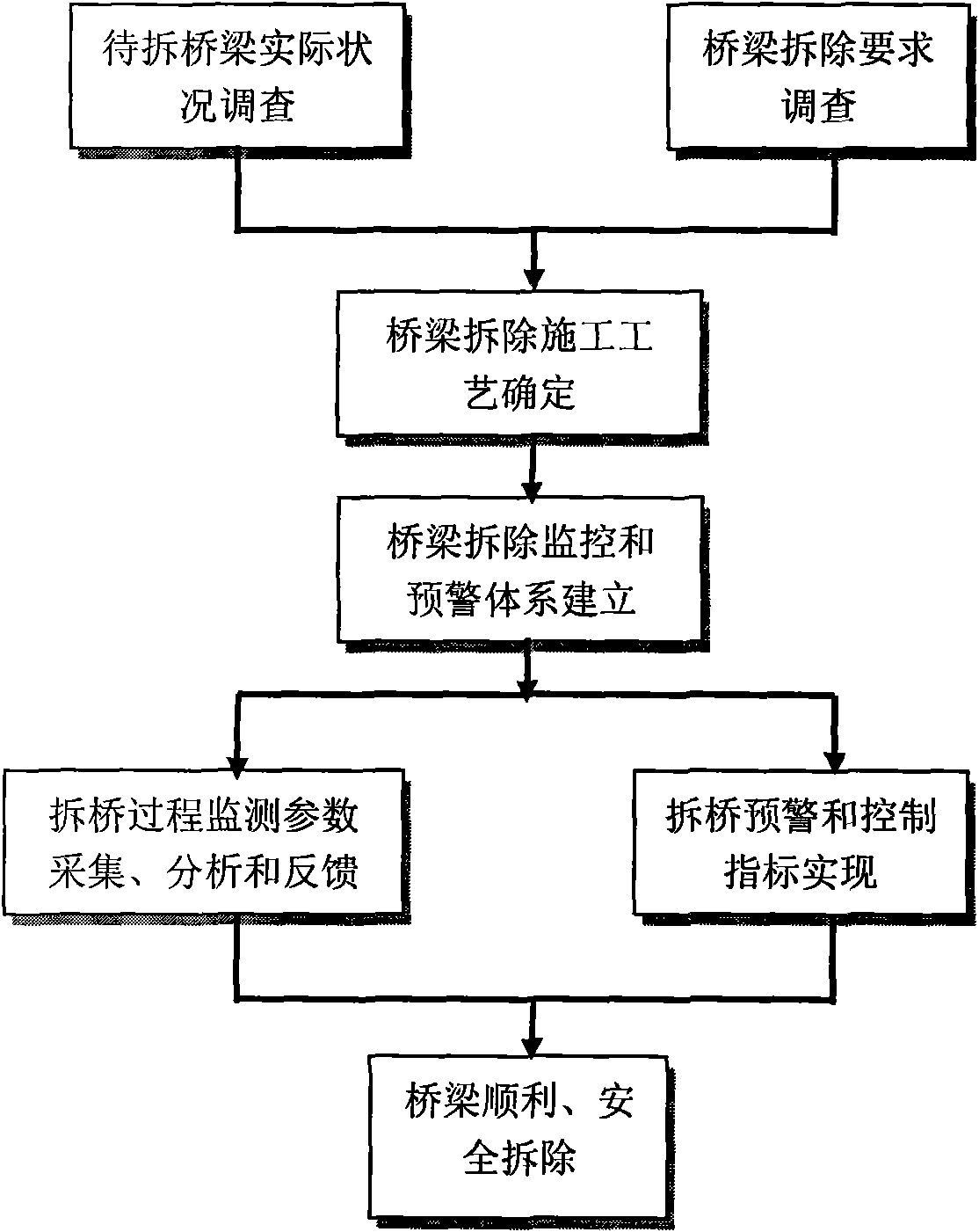
The invention relates to a method for monitoring construction of channel bridge demolition, which carries out process monitoring, control and pre-warning on the construction of channel bridge demolition. The technical scheme for realizing the invention is as follows: the method comprises the following steps: determining a bridge demolishing scheme combining the actual condition of a bridge to be demolished and the requirements of peripheral environment; establishing an structural simulation analytic system; establishing a finite element simulation computation model of bridge-completion state according to bridge-completion structural sequence; carrying out calculation and analysis on structural reverse demolition according to bridge demolishing sequence to obtain actual deformation and stress state at each stage in the structural construction process; establishing a theory pre-warning indicator; establishing a field monitoring system aiming at bridge demolishing process; carrying out acquisition and analysis on the monitoring parameters in the demolishing process of the bridge; feeding back the analyzed result to the structural simulation analysis system; establishing a constructionpre-warning system, carrying out safety and quality judgment in the bridge demolishing process to realize the pre-warning and controlling indication.

Description

technical field [0001] The invention relates to the field of bridge construction, in particular to a monitoring method for dismantling and constructing a channel bridge. Background technique [0002] Bridge demolition is a special bridge construction work with great technical difficulty and high safety risks. At present, the construction technology and methods in the direction of bridge demolition in China are not systematic enough, perfect and mature enough, especially for channel bridges. At the same time of demolition, factors such as navigation safety and environmental protection need to be met. Therefore, in order to achieve the purpose of dismantling bridges safely, smoothly, quickly and environmentally friendly, it is particularly important to monitor and warn the dismantling process of channel bridges. [0003] Compared with the construction of new bridges, bridge demolition work has higher requirements on the grasp of construction technology, safety monitoring and ...

Claims


Application Information

Patent Timeline
Patent Type & Authority Applications(China)
IPC IPC(8): E01D24/00G06F17/50
Inventor 承宇赖广胜李运喜
Owner JIANGSU TRANSPORTATION RES INST CO LTD
Learn More