
Climate compensator

A technology for climate compensation and display circuits, which is applied to household heating, lighting and heating equipment, household heating, etc., and can solve problems such as inconvenience of use and complexity of curve setting.

Inactive Publication Date: 2010-02-10
BEIJING ACME GRAMS THERMAL SCI & TECH DEV CO LTD
View PDF0 Cites 8 Cited by
  • Summary
  • Abstract
  • Description
  • Claims
  • Application Information

AI Technical Summary

Problems solved by technology

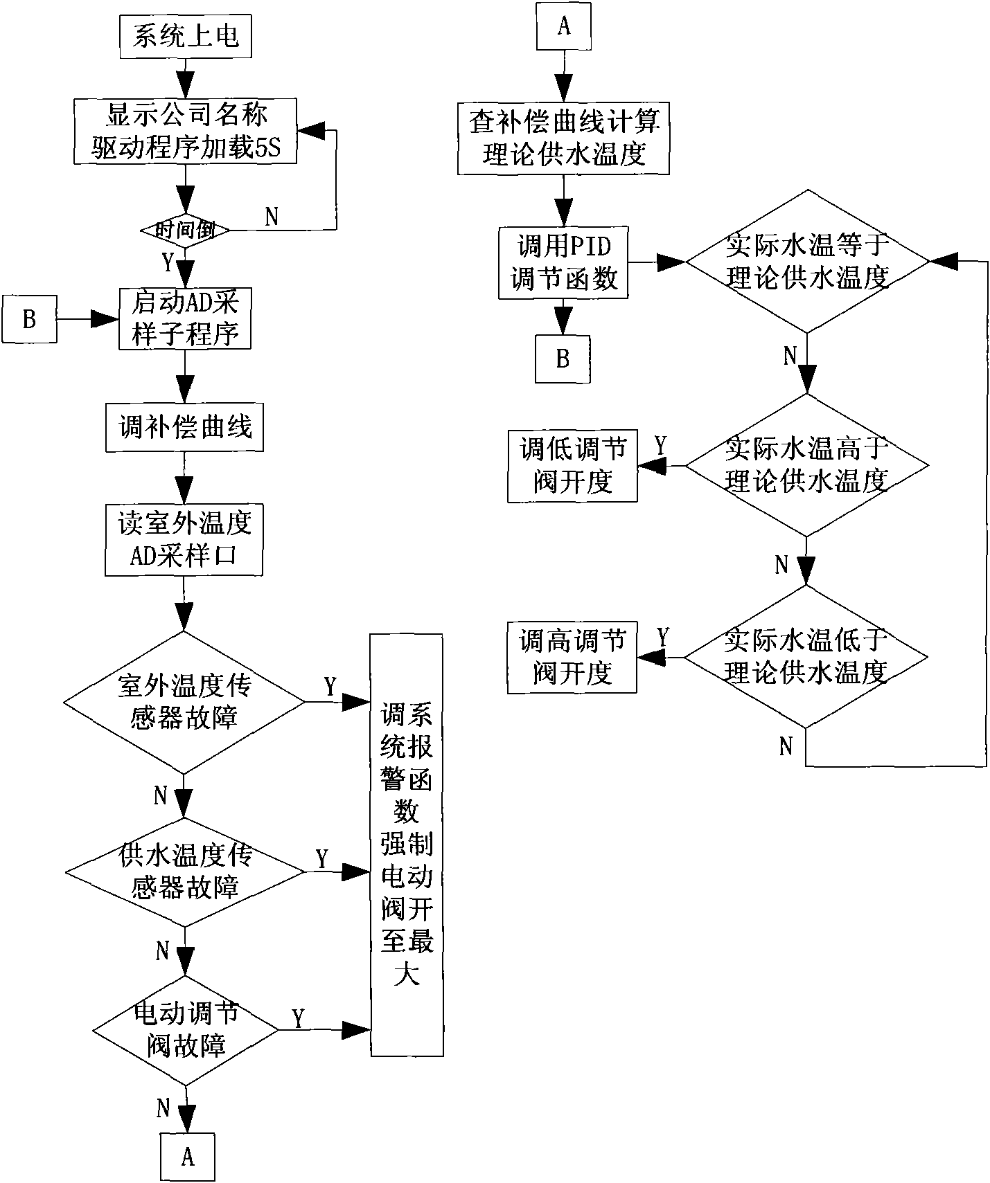
[0003] In order to overcome the complexity and inconvenient use of the existing climate compensator curve setting, the utility model provides a climate compensator, which can not only set the curve conveniently, but also can use the self-learning function, Real-time automatic adjustment of the curve to find the appropriate water supply temperature, automatic control of the water supply temperature, and the use of Chinese liquid crystal display, keyboard operation, so that users can easily set parameters and use, while increasing the network communication function

Method used


Image

  • Climate compensator
  • Climate compensator
  • Climate compensator

Examples


Embodiment Construction

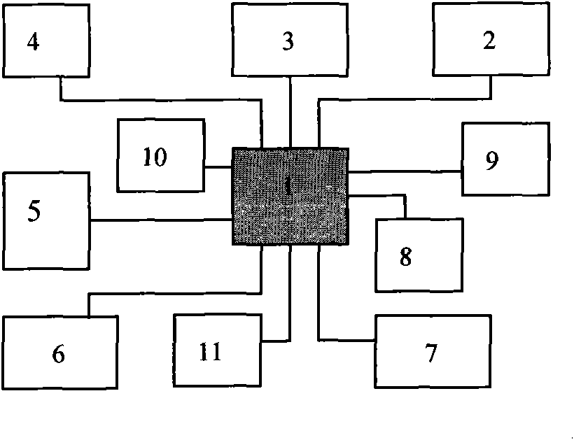
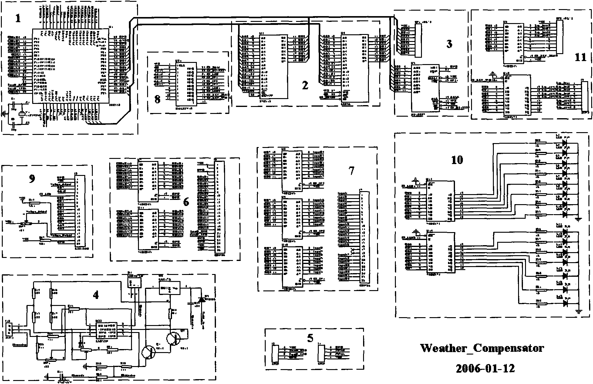
[0012] The storage circuit (2) is arranged in the upper right corner of the main circuit control chip, that is, the main CPU (1), the (3) clock circuit is arranged directly above, the (4) eight-way acquisition circuit is arranged in the upper left corner, and the (10) operation instruction is arranged in the right left Circuit and (5) communication circuit and PWM output interface, (6) control output circuit is arranged in the lower left corner, (11) keyboard input circuit is arranged directly below, (7) acquisition input circuit is arranged in the lower right corner, and (8) pieces are arranged in the right right Selection circuit and (9) display circuit.

[0013] After the climate compensator system is powered on, the signal is collected through the collection circuit (4), that is, the outdoor temperature, water supply temperature, and return water temperature sensor signals are converted into 4-20mA current signals, which are connected to the main CPU (1), and at the same ti...


PUM


Abstract

The invention provides a climate compensator for saving energy, which is mainly applied to a central heating system. The compensator essentially consists of a CPU circuit, a top right corner memory circuit, a right above clock circuit, a top left corner three-way acquisition circuits, a right left operating indicating circuit, a communication circuit and a PWM output interface, a left lower cornercontrolling outputting circuit, a right below keyboard input circuit, a right lower corner acquiring inputting circuit, a right chip selecting circuit and a display circuit. According to the change of the outdoor temperature, an outdoor temperature parameter is acquired by the acquiring circuit; and according to a set temperature-water supplying compensation curve and by computing with a main CPU, the climate compensator solves a proper water supplying temperature, automatically controls the water supplying temperature by adjusting an electric three-way valve to change the water flow size ofa pipeline, and realizes the climate compensation of the water supplying temperature and the outdoor temperature of a heat supplying system, so as to guarantee that a heating object (room temperature)to be stabilized in a temperature range needed by a customer.

Description

Technical field: [0001] The utility model relates to a central heating system for the purpose of energy saving. According to the change of the outdoor temperature in the central heating system, by collecting the outdoor temperature parameters, the appropriate adjustment water supply temperature can be obtained according to the set curve, and the water supply temperature can be automatically controlled to realize heat supply. Climate compensation of water supply temperature in the system to ensure that the heating object (room temperature) is stable within the temperature range required by the user. Background technique: [0002] At present, the known climate compensator is produced abroad and consists of indicating scale, knob, time relay, signal acquisition and output. The climate compensator controls the water supply temperature by collecting the outdoor temperature and changing the outdoor temperature to achieve the purpose of energy saving. However, due to differences in...

Claims


Application Information

Patent Timeline
Patent Type & Authority Applications(China)
IPC IPC(8): F24D19/10
Inventor 赵连明肖永明吴修所
Owner BEIJING ACME GRAMS THERMAL SCI & TECH DEV CO LTD
Learn More