Direct backlight module

A backlight module, direct-type technology, applied in the field of direct-type backlight modules, can solve the problems of increasing power consumption, difficulty in meeting thin design, and reducing the brightness of outgoing light

Inactive Publication Date: 2010-02-10
HONG FU JIN PRECISION IND (SHENZHEN) CO LTD +1
View PDF0 Cites 8 Cited by
  • Summary
  • Abstract
  • Description
  • Claims
  • Application Information

AI Technical Summary

Problems solved by technology

However, increasing the depth of the frame will reduce the brightness of the outgoing light and lead to a larger thickness of the backlight module 1

Method used


Image

  • Direct backlight module
  • Direct backlight module
  • Direct backlight module

Examples


Embodiment Construction

[0016] The direct type backlight module 200 of the present invention will be further described in detail below with reference to the drawings and embodiments.

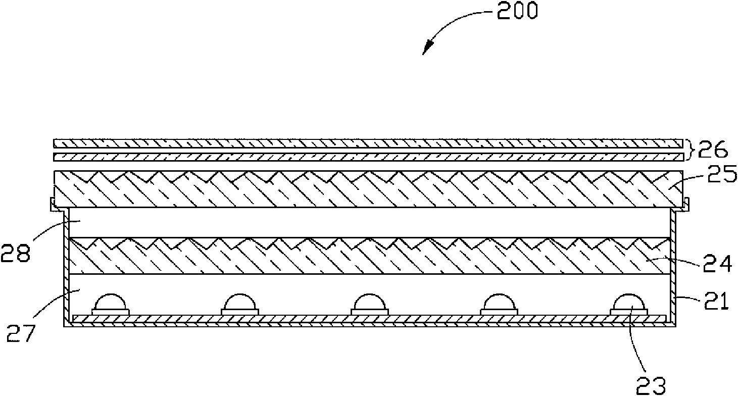
[0017] See figure 2 , shows the direct type backlight module 200 according to the first embodiment of the present invention, which includes a frame 21 , a plurality of LEDs 23 , a first optical plate 24 , a second optical plate 25 and a plurality of optical sheets 26 . Wherein a plurality of light emitting diodes 23 are arranged at the bottom of the frame 21, and the first optical plate 24 and the second optical plate 25 are sequentially arranged above the light emitting diodes 23 at intervals, thereby dividing the frame 21 into first and second diffusion spaces 27, 28, more An optical sheet 26 is disposed above the second optical plate 25 .

[0018] The frame 21 may be made of metal or plastic with high reflectivity, or metal or plastic coated with a high reflectivity coating.

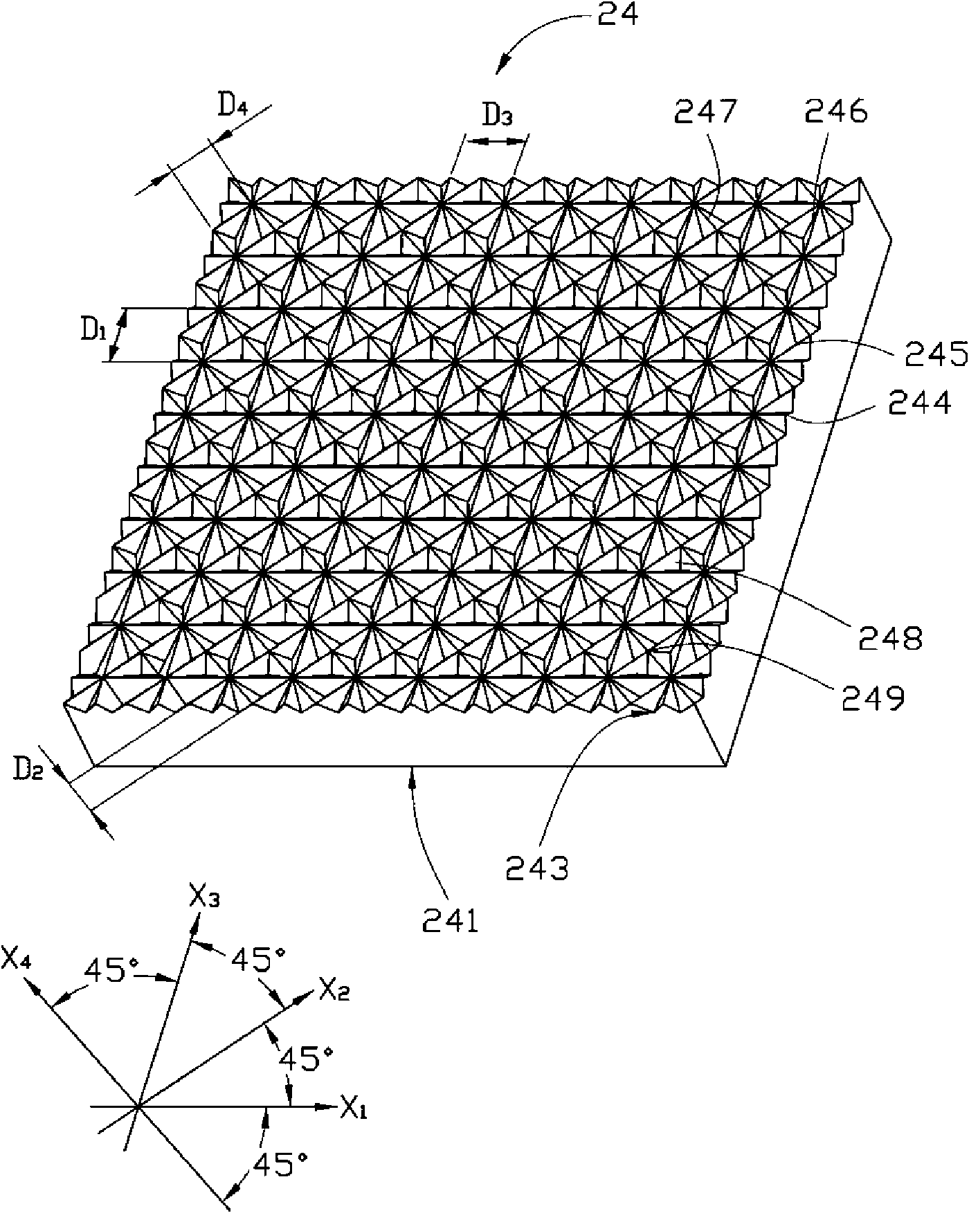
[0019] See image 3 and Figure 4 ...


PUM


Abstract

The invention relates to a direct backlight module which comprises a frame, a plurality of light-emitting diodes arranged at the bottom of the frame, as well as a first optical plate and a second optical plate that are sequentially arranged above the light-emitting diodes at intervals, wherein the first optical plate and the second optical plate respectively comprise a light entry surface and a light exit surface which is opposite to the light entry surface, as well as a plurality of long-strip V-shaped ridge structures which are formed at the light exit surface, extend along at least two different directions and are mutually staggered. The direct backlight module has better exit ray uniformity and is suitable for thinned design.

Description

technical field [0001] The invention relates to a direct type backlight module, in particular to a direct type backlight module applied to liquid crystal displays. Background technique [0002] Liquid crystal display devices are widely used in electronic products such as personal digital assistants, notebook computers, digital cameras, mobile phones, and LCD TVs. However, since the liquid crystal display device itself cannot emit light, it needs a backlight module to produce a display function. [0003] See figure 1 , a backlight module 100, which includes a frame 10, a reflector 12, a plurality of LED (light emitting diode) point light sources 14, a diffusion plate 16 and a plurality of optical sheets 18. The plurality of LED point light sources 14 are disposed on the bottom plate of the frame 10 , and the plurality of optical sheets 18 cover the opening of the frame 10 . The diffusion plate 16 is arranged between the LED point light sources 14 and the plurality of optic...

Claims


Application Information

Patent Timeline
IPC IPC(8): G02F1/13357G02B6/00F21V21/00F21V8/00
Inventor 章绍汉
Owner HONG FU JIN PRECISION IND (SHENZHEN) CO LTD
Why Eureka
Try Eureka