
Automatic darkening and glare reducing liquid crystal mirror

A reflective mirror and liquid crystal technology, applied in the field of reflective mirrors, can solve the problems that reflective mirrors are not feasible

Inactive Publication Date: 2010-02-10
OPTI SOURCE
View PDF7 Cites 4 Cited by
  • Summary
  • Abstract
  • Description
  • Claims
  • Application Information

AI Technical Summary

Problems solved by technology

While taking power from the vehicle's battery may be acceptable for original equipment manufacture (OEM) products, it is not feasible for after-market reflectors where customers require the reflector to be self-contained without any external wiring unit

Method used


Image

  • Automatic darkening and glare reducing liquid crystal mirror
  • Automatic darkening and glare reducing liquid crystal mirror
  • Automatic darkening and glare reducing liquid crystal mirror

Examples


Embodiment Construction

[0017] Before discussing the present invention in detail with reference to the accompanying drawings, several aspects of the mirror system of the present invention and its electronic control system will be described in order to understand the detailed description that follows. These aspects include the various components of the LC chemistry system as well as the mirror control electronics.

[0018] 1. LC chemical system

[0019] The performance of the LC mirrors of the present invention is dependent on the chemical system, which includes the nature and properties of the alignment compounds used for the LC molecules and their closely related LC material formulations. Certain LC fluids with dichroic dyes work consistently with oriented compounds already formed. The two materials must be compatible and mix well to establish the LC molecular orientation required for maximum optical performance. With the LC techniques described herein, two types of LC mirrors can be constructed. ...


PUM


Abstract

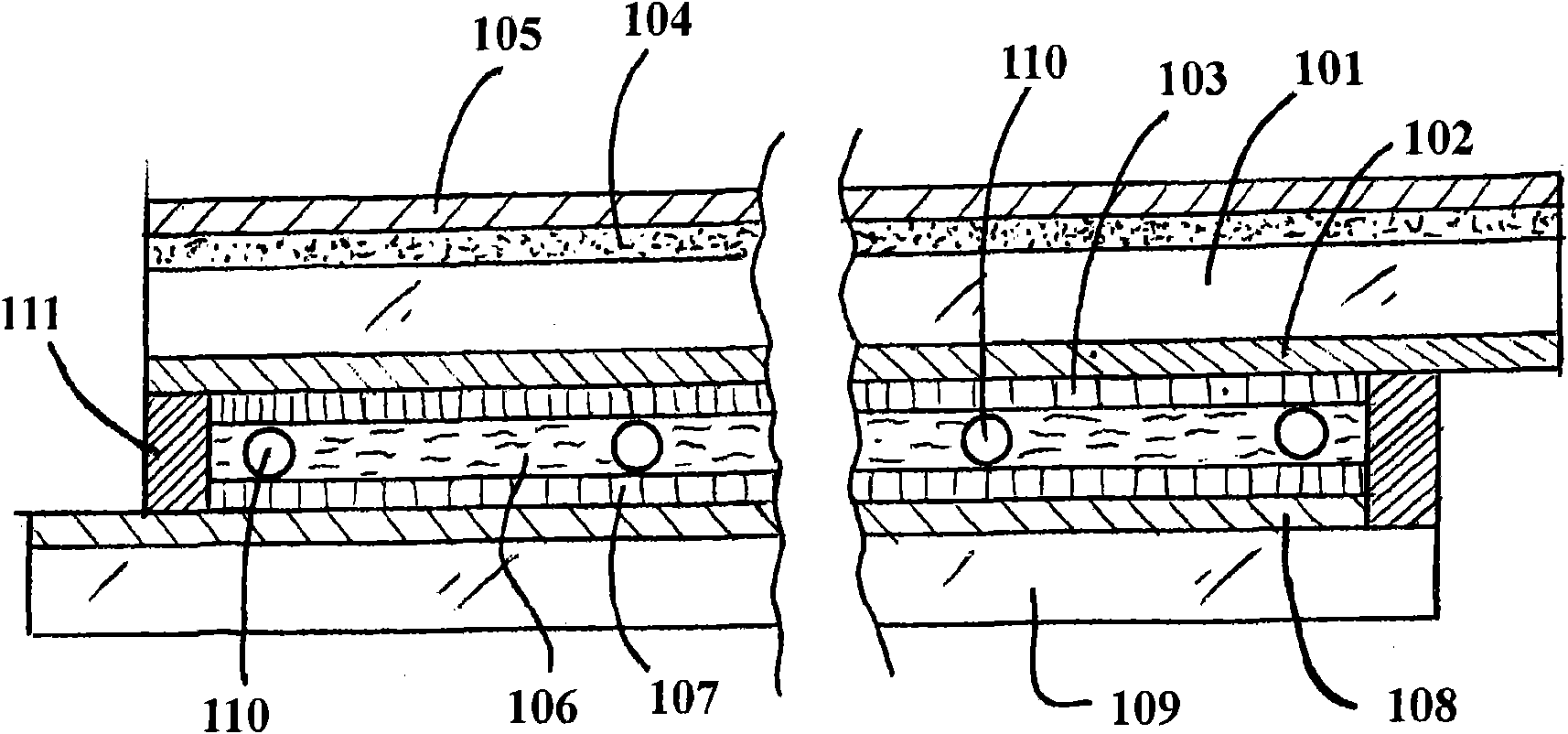
An automatic darkening and glare reducing liquid crystal mirror for vehicles is disclosed. The mirror has a front substrate (101) of transparent glass or plastic and a back substrate (109) of glass orplastic with a highly reflective or transflective mirrored coating (108). The front and back substrates are spaced apart a small distance to define a liquid crystal cell between the substrates and aliquid crystal fluid (106) incorporating dichroic dyes is contained within the liquid crystal cell. A conductive thin film (102) is applied onto the interior surface of the front substrate and the reflective or transflective coating (108) of the back substrate also is conductive. An alignment compound is deposited on the conductive thin film (102) and on the reflective or transflective coating (108) and the alignment compound bounds the liquid crystal cell. An electronic control circuit is adapted to apply selectively a voltage signal to the conductive thin film and the reflective or transflective coating (108) to affect the transmittance of the liquid crystal fluid, and thereby the darkness of the mirror. The nature of the alignment compound determines a home or rest alignment of the liquid crystal molecules, either parallel or perpendicular to the substrates, and thus determines whether the mirror is normally dark (a 'dark mode' mirror) or normally bright (a 'bright mode' mirror). Application of a voltage signal to a dark mode mirror lightens it while application of a voltage signal to a bright mode mirror darkens the mirror. A headlight sensor (302) and an ambient sensor (301) are coupled to the electronic control circuit and the circuit is configured to darken the mirror in response to signals from the sensors indicating that the ambient light intensity is below a predetermined threshold (equivalent to nighttime) and the intensity of light from headlights impinging on the mirror is above a predetermined threshold (equivalent to a glare condition).

Description

technical field [0001] The invention relates to a reflector. Background technique [0002] For driving safety and comfort, there has long been a need to control the reflectivity of rearview mirrors in automobiles and other motor vehicles. Mirror reflectance can be changed from a highly reflective or "bright mode" (BM) state to a less reflective "dark mode" (DM) state at driver preference. When other vehicles with bright headlights approach from behind at night, the mirror transitions from its BM state to its DM state to minimize headlight glare reflections from the mirror, since the nuisance light intensity can hinder the driver Operate the vehicle safely. Conventionally, this adjustment is manually controlled by tilting the mirror reflection angle slightly away from the driver's mechanical lever. Later, mechanical levers were controlled by electromechanical components, but still by the driver when requested. Recently, rearview mirrors have been marketed using electrochr...

Claims


Application Information

Patent Timeline
IPC IPC(8): G02F1/29G02F1/133B60R1/02
CPCG02F1/13306G02F1/133553G02F1/13725G02F1/133555B60R1/088G02F1/13318
Inventor W·Y·温R·海恩斯C·T·常
Owner OPTI SOURCE
Learn More