Laminated electric connector

A technology of electrical connectors and connectors, which is applied in the direction of connection, fixed connection, and parts of connection devices, etc., can solve the problems of shrinking the motherboard, achieve the effects of shortening thickness, reducing footprint configuration, and preventing electromagnetic interference

Active Publication Date: 2010-02-10
PEGATRON
View PDF0 Cites 2 Cited by
  • Summary
  • Abstract
  • Description
  • Claims
  • Application Information

AI Technical Summary

Problems solved by technology

Therefore, there are currently stacked electrical connectors on the market, but they only simply stack up their respective connectors, and the total pin area of ​​the motherboard is only the addition of their independent areas.
In addition, after the independent connectors are stacked, the exposed parts of the signal-conducting terminals (pins) will be more, that is, the chances of signal interference will be greater, especially for connectors that are stacked above (farther from the motherboard). Connectors have a greater impact
[0003] Therefore, the improvement of the existing stacked electrical connector is only to save the available and limited peripheral area of ​​the main board, and the corresponding footprint (footprint) configuration area on the main board does not actually decrease. not much help

Method used


Image

  • Laminated electric connector
  • Laminated electric connector
  • Laminated electric connector

Examples


Embodiment Construction

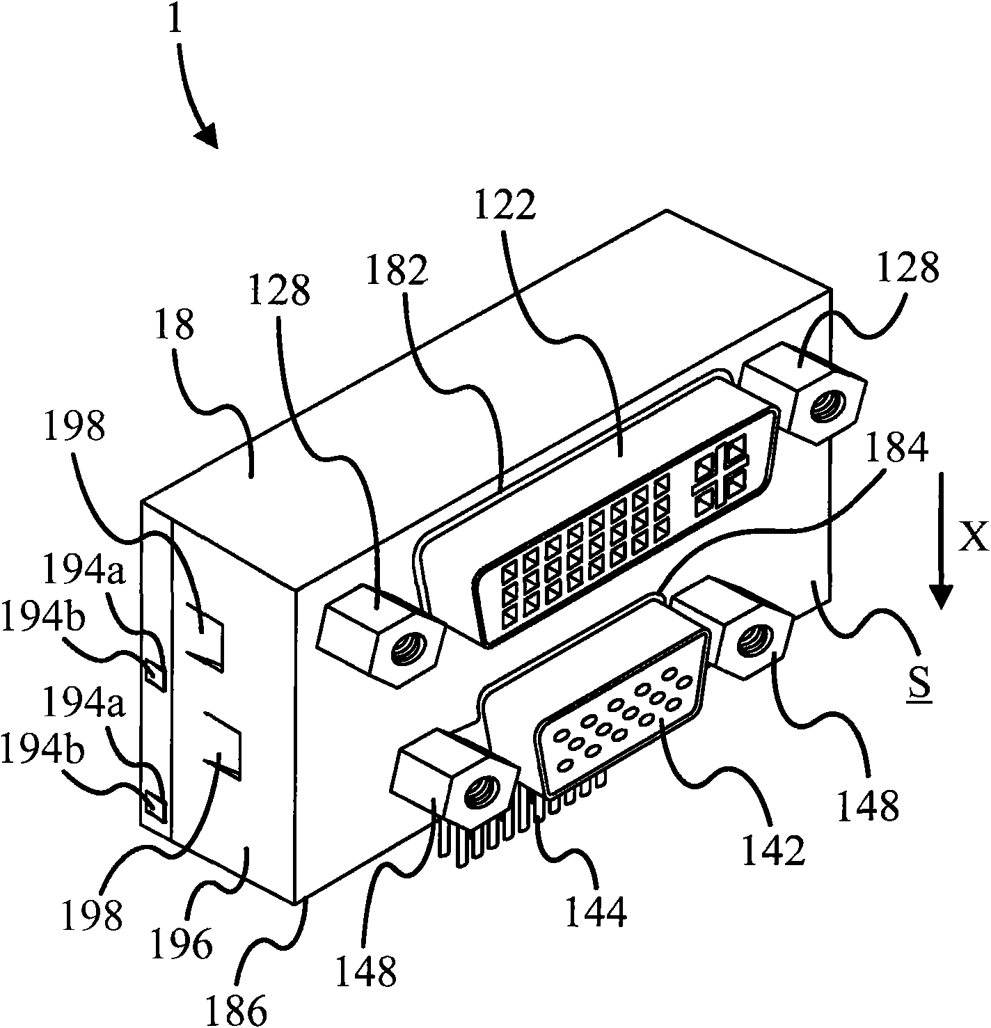
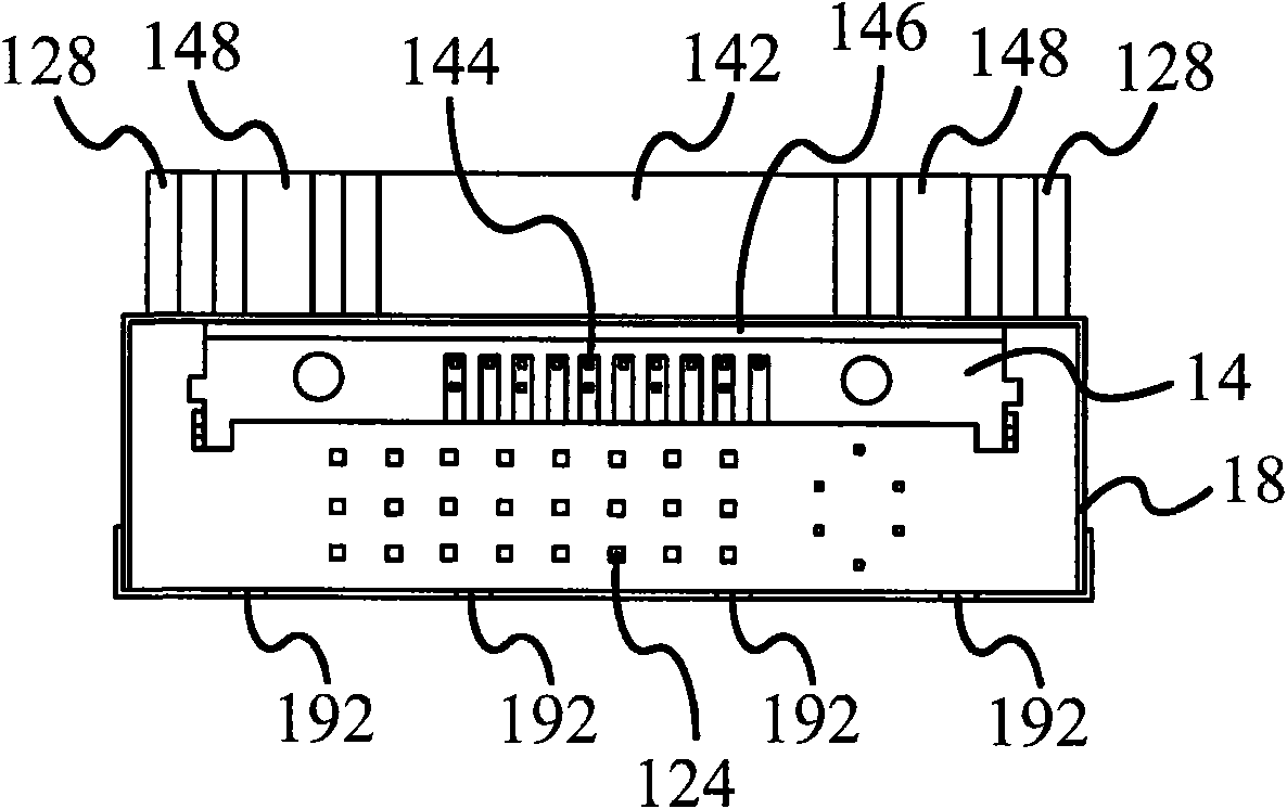
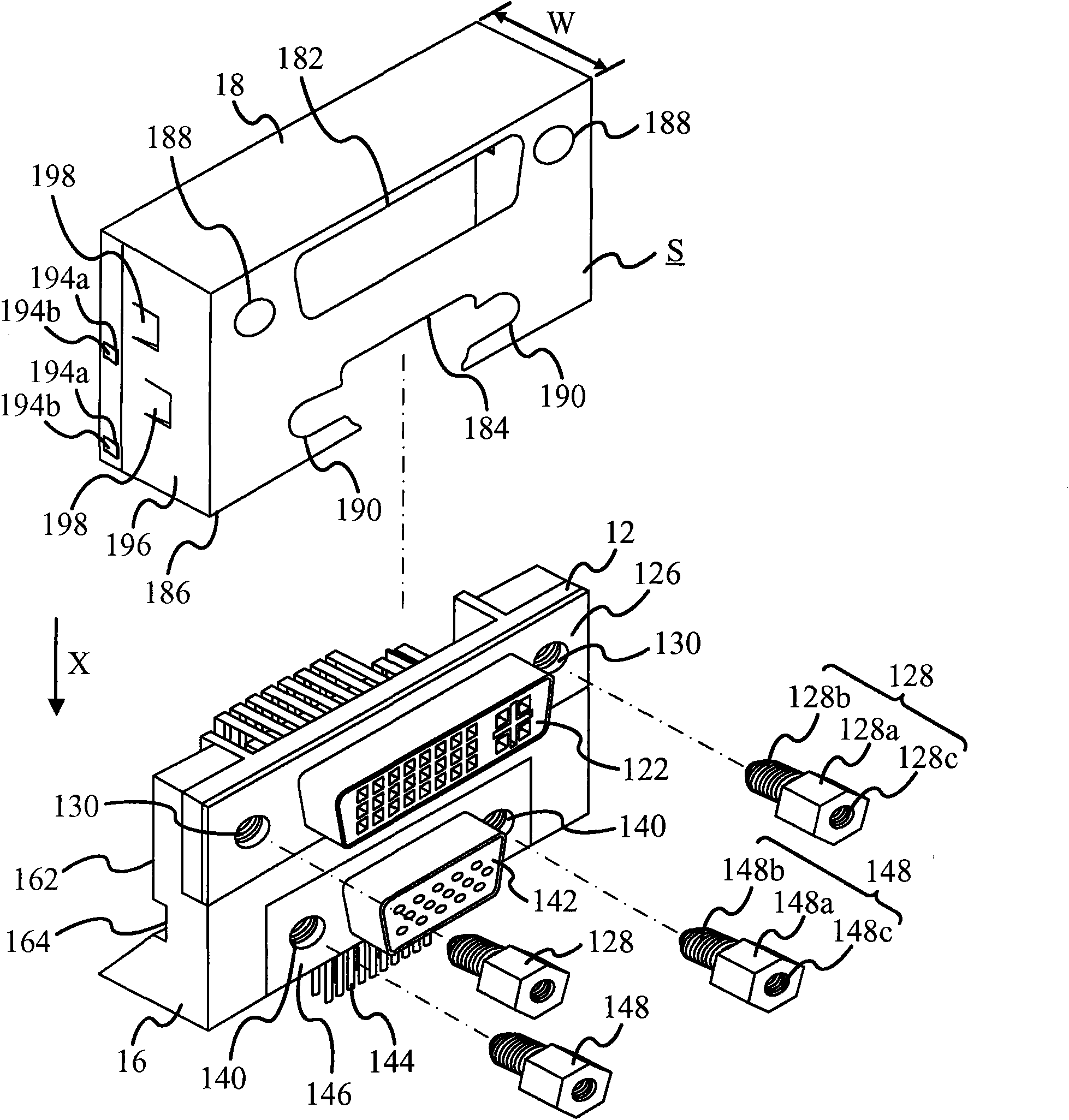
[0015] see figure 1 , figure 2 and image 3 . figure 1 Shown is a perspective view of a stacked electrical connector 1 according to a preferred embodiment of the present invention, figure 2 Shown is a bottom view of the stacked electrical connector 1, image 3 Shown is a partial exploded view of the stacked electrical connector 1 . The stacked electrical connector 1 includes a first connector 12 , a second connector 14 , a frame 16 and a conductive shell 18 . The first connector 12 and the second connector 14 are connected by the frame 16 , and the conductive shell 18 covers the first connector 12 , the second connector 14 and the frame 16 at the same time.

[0016] Wherein, the first connector 12 includes a first signal connection portion 122 and a first group of soldering legs 124 (mark one of them), and the first group of soldering legs 124 extends along the direction X. The second connector 14 includes a second signal connector 142 and a second set of soldering pin...


PUM


Abstract

The invention discloses a laminated electric connector, which comprises a first connector, a second connector and a conductive shell. The first connector comprises a first signal connecting part and afirst group of welding feet, and the first group of welding feet extend along a direction. The second connector comprises a second signal connecting part and a second group of welding feet, and the second group of welding feet extend along the direction. The first connector is stacked on the second connector. The conductive shell comprises a first opening, a second opening and a third opening. The conductive shell covers the first connector and the second connector, the first signal connecting part passes through the first opening, the second signal connecting part passes through the second opening, and the first group of welding feet and the second group of welding feet are exposed at the third opening. Therefore, the conductive shell can shield outside interference, so the electric connector still can perform reliable signal transmission under the laminated structure.

Description

technical field [0001] The invention relates to a laminated electrical connector, in particular to a laminated electrical connector with full shielding. Background technique [0002] With the development of electronic technology, the types of computer peripheral devices are increasing day by day. Even for devices with similar functions, the connection interfaces used there are also many specifications. Due to the geometric constraints of the main board and the housing housing the main board, it is unfeasible to independently arrange all the connection interfaces around the main board. Therefore, there are currently stacked electrical connectors on the market, but they only simply stack up their respective connectors, and the total pin area of ​​the main board is only the sum of the independent areas. In addition, after the independent connectors are stacked, the exposed parts of the signal-conducting terminals (pins) will be more, that is, the chances of signal interference...

Claims


Application Information

Patent Timeline
Patent Type & Authority Applications(China)
IPC IPC(8): H01R12/02H01R13/518H01R27/00H01R12/50
Inventor 李新乐蔡豪哲吴瑞钦麦世达
Owner PEGATRON
Why Eureka
Try Eureka