Permanent magnet synchronous motor rotor integration stamped sheet used for oil-field oil pumper

A technology of permanent magnet synchronous motor and pumping unit, which is applied in the directions of magnetic circuit rotating parts, magnetic circuit shape/style/structure, mining fluid, etc., and can solve the problem of incomplete radial distribution of magnetic poles and increased randomness of magnetic pole distribution , The squirrel cage cannot be formed at one time, etc., to achieve the effect of eliminating the imbalance of the rotor, stable size, and smooth operation of the motor

Inactive Publication Date: 2010-02-10
无锡市华东钢业机械有限公司
View PDF0 Cites 6 Cited by
  • Summary
  • Abstract
  • Description
  • Claims
  • Application Information

AI Technical Summary

Problems solved by technology

Each independent magnetic pole is made by laminating several magnetic pole punches. Each independent magnetic pole surrounds the motor shaft with a certain gap, and is fixed on the magnetic isolation sleeve by bolts, and several copper strips are penetrated in the magnetic pole along the axial direction. The rotor starting squirrel cage is formed by welding with the end rings at both ends; therefore, the randomness of the magnetic pole distribution will increase, the accumulated error will increase, and the assembled magnetic poles will not be completely uniform in the radial direction of the motor shaft.
In addition, the overall unbalance of the rotor will be increased, and the width of the gap between the magnetic poles (that is, the magnetic steel groove for placing the magnetic steel) will vary, resulting in difficulty in assembling the magnetic steel and causing the broken magnetic steel; the rotor starting squirrel cage cannot be formed at one time. Manual welding is required, large consumables, cumbersome production, waste of manpower and material resources, and reduced production efficiency

Method used


Image

  • Permanent magnet synchronous motor rotor integration stamped sheet used for oil-field oil pumper
  • Permanent magnet synchronous motor rotor integration stamped sheet used for oil-field oil pumper
  • Permanent magnet synchronous motor rotor integration stamped sheet used for oil-field oil pumper

Examples


Embodiment Construction

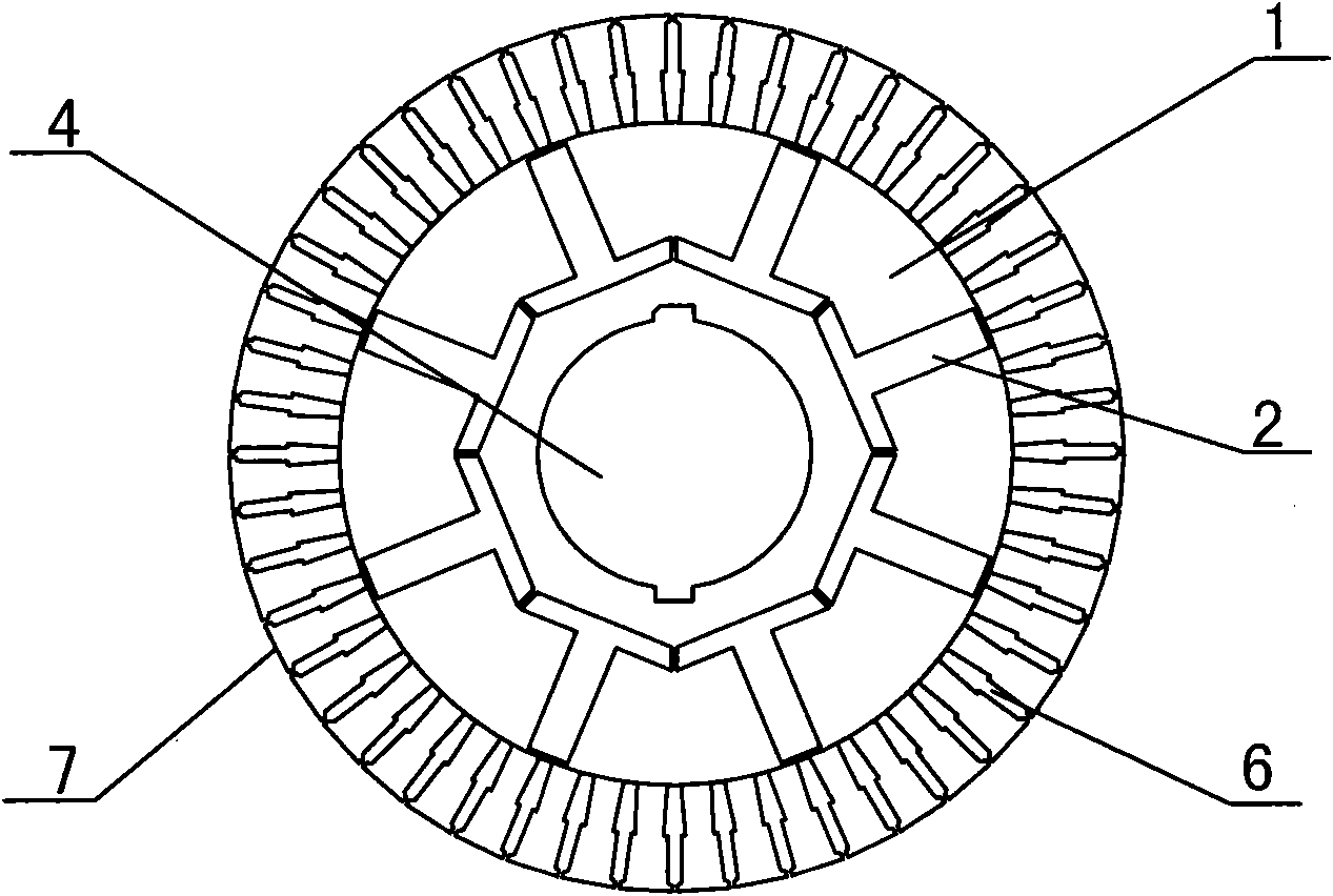
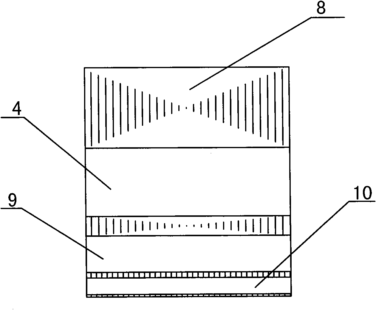
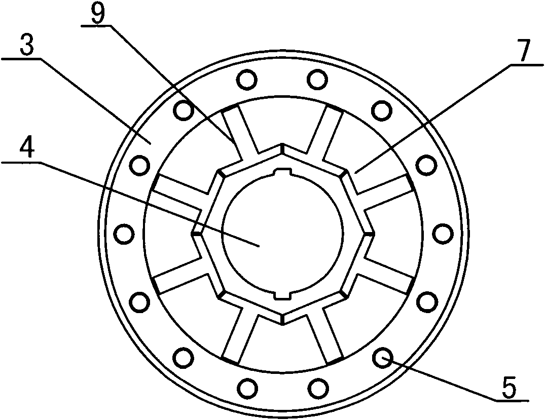
[0017] As shown in Fig. 14, the permanent magnet synchronous motor rotor integrated rotor body 7 for oil pumping units according to the present invention includes a magnetic pole piece 1 and a magnetic steel hole 2, and the magnetic pole piece 1 is along the circumference of the motor shaft hole 4. It is arranged as an integral structure and forms the rotor stamping body 7, a magnetic steel hole 2 is provided between every two adjacent magnetic pole pieces 1, and a ring of squirrel cage guide bar holes 6 is provided on the outer ring of the magnetic pole piece 1. A plurality of rotor stamping bodies 7 are laminated to form a rotor body 8; the rotor body is composed of magnetic steel holes 2 to form magnetic steel slots 9 with open ends; the rotor body is composed of guide bar holes to form guide bar slots 10; The rotor body 8 utilizes a mold to inject aluminum into the guide bar groove, and while the guide bar 11 is formed in the guide bar groove 10, the end ring 3 and the bala...


PUM


Abstract

The invention provides a permanent magnet synchronous motor rotor integration stamped sheet used for an oil-field oil pumper, comprising magnetic pole pieces and a magnetic steel tank, wherein the magnetic pole pieces are arranged into an integration structure along the periphery of motor revolving shaft hole, a magnetic steel mounting hole is arranged between each two adjacent magnetic pole pieces, a circle of conducting bar holes used for casting and starting mouse cage conducting bars and end rings at the outer ring of the magnetic pole pieces, and after a plurality of rotor stamped sheetsare overlapped and pressed, a channel with two ends open, namely the magnetic steel tank is formed by the magnetic steel holes. The invention eliminates the phenomenon of unbalanced rotor caused by assembling error of the original plural independent magnetic pole pieces, reduces vibration of the motor in operation, eliminates the problem of uneven width of the original magnetic steel tank, and improves work efficiency of magnetic steel assembling; the distribution of magnetic steel tank and magnetic pole pieces are even, and the motor operation is more stable; as the rotor stamped sheets forman integration structure, thus reducing production cost and labor intensity and greatly improving productivity.

Description

technical field [0001] The invention relates to the field of permanent magnet synchronous motors, in particular to an integrated stamping plate for a permanent magnet synchronous motor rotor used in an oil field pumping unit. Background technique [0002] At present, in the field of permanent magnet synchronous motors for oil pumping units, the rotor structure is formed by distributing mutually independent magnetic poles equal to the number of magnetic poles around the circumference of the rotating shaft according to the number of poles of the motor. Each independent magnetic pole is made by laminating several magnetic pole punches. Each independent magnetic pole surrounds the motor shaft with a certain gap, and is fixed on the magnetic isolation sleeve by bolts, and several copper strips are penetrated in the magnetic pole along the axial direction. It is welded with the end rings at both ends to form a rotor starting squirrel cage; therefore, it will lead to an increase in...

Claims


Application Information

Patent Timeline
Patent Type & Authority Applications(China)
IPC IPC(8): H02K1/27E21B43/00
Inventor 沈澄
Owner 无锡市华东钢业机械有限公司
Why Eureka
Try Eureka