Led drive circuit
A LED drive and circuit technology, applied in circuit layout, lamp circuit layout, electric light source, etc., can solve the problems of application restrictions, low rated power, low rated voltage, etc.
- Summary
- Abstract
- Description
- Claims
- Application Information
AI Technical Summary
Problems solved by technology
Method used
Image
Examples
no. 1 example
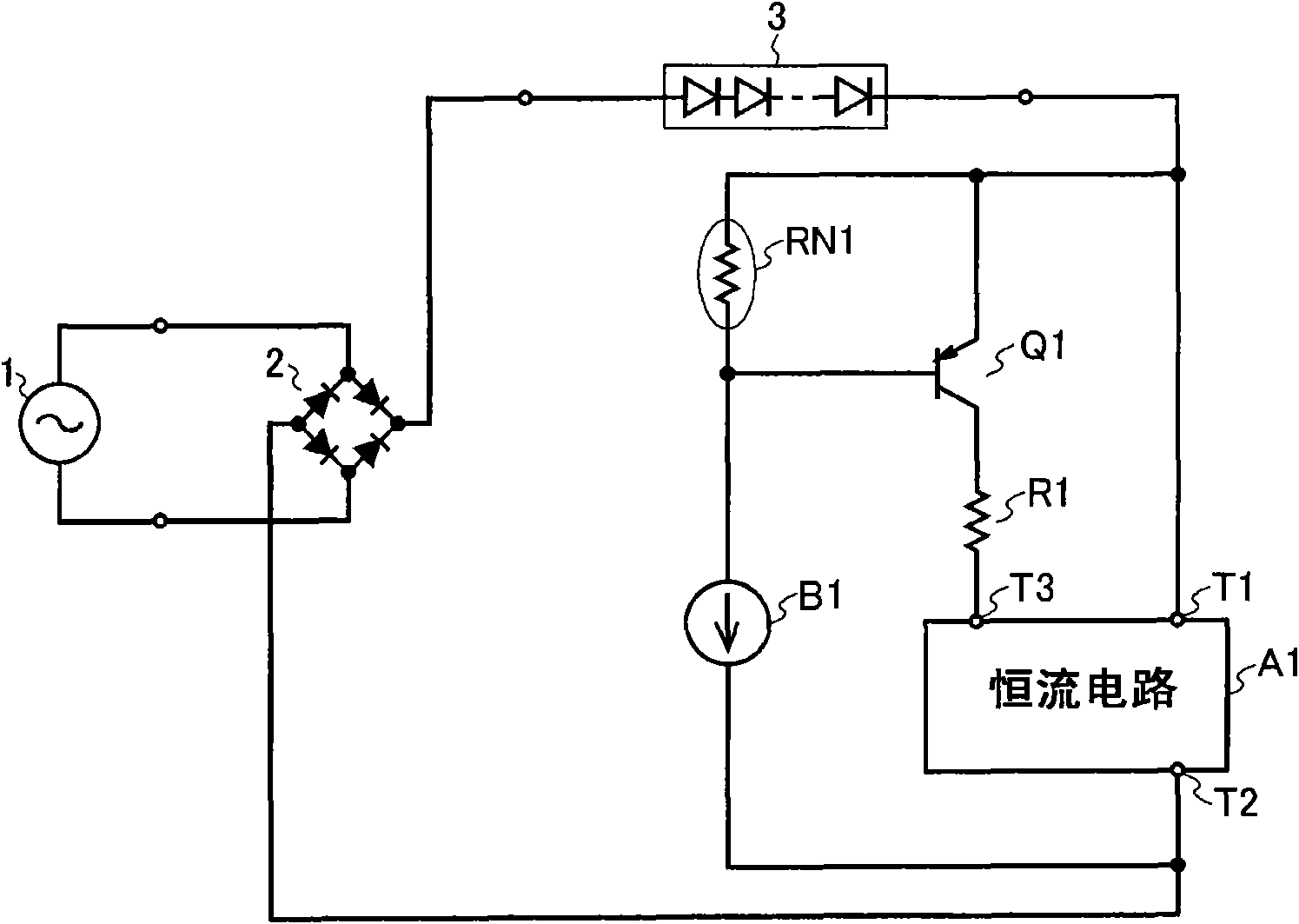
[0050] figure 1 The configuration of the LED driving circuit according to the first embodiment of the present invention is shown in . figure 1 The LED driving circuit of this embodiment shown includes: a bridge diode 2; constant current circuits A1 and B1; a PNP transistor Q1; a resistor R1; and a negative temperature coefficient resistor RN1 such as an NTC thermistor (hereinafter referred to as "NTC resistor RN1").
[0051] The input end of the bridge diode 2 is connected to the commercial AC100V power supply 1 , and one output end of the bridge diode 2 is connected to the anode of the LED module 3 . The constant current terminal T1 of the constant current circuit A1 is connected to the cathode of the LED module 3 , and the constant current terminal T2 of the constant current circuit A1 is connected to the other output end of the bridge diode 2 . The emitter of the PNP transistor Q1 is connected to the cathode of the LED module 3 , and the collector of the PNP transistor ...
no. 2 example
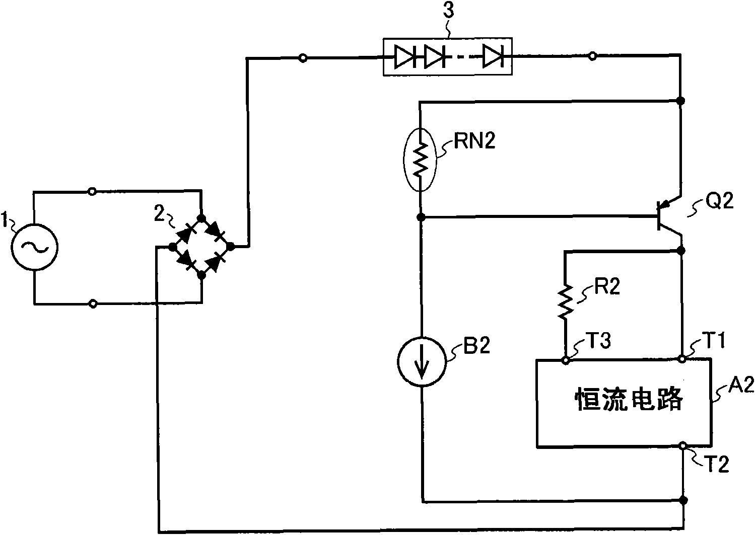
[0058] figure 2 The configuration of the LED driving circuit according to the second embodiment of the present invention is shown in . figure 2 The LED driving circuit of this embodiment shown is provided with: a bridge diode 2; constant current circuits A2 and B2; a PNP transistor Q2; a resistor R2; and a negative temperature coefficient resistor (hereinafter referred to as "NTC resistor") RN2.
[0059]The input end of the bridge diode 2 is connected to the commercial AC100V power supply 1 , and one output end of the bridge diode 2 is connected to the anode of the LED module 3 . The cathode of the LED module 3 is connected to the emitter of the PNP transistor Q2. The constant current terminal T1 of the constant current circuit A2 is connected to the collector of the PNP transistor Q2 , and the constant current terminal T2 of the constant current circuit A2 is connected to the other output terminal of the bridge diode 2 . Also, the collector of the PNP transistor Q2 is con...
no. 3 example
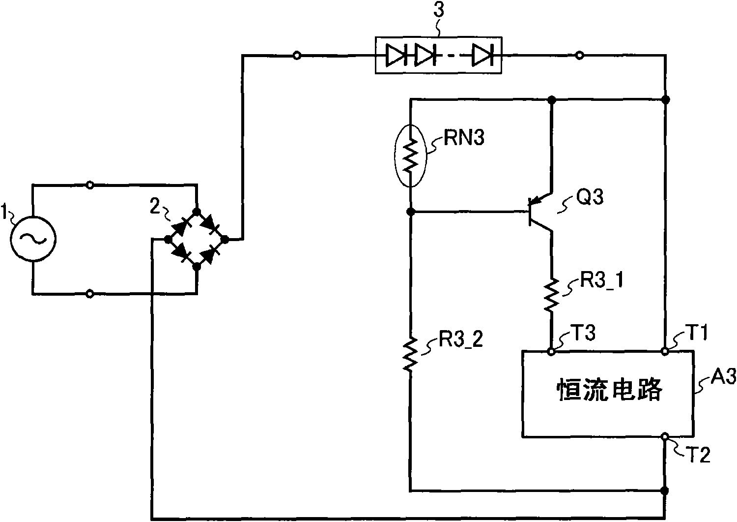
[0065] image 3 The configuration of the LED driving circuit according to the third embodiment of the present invention is shown in . image 3 The LED driving circuit shown in this embodiment includes: a bridge diode 2; a constant current circuit A3; a PNP transistor Q3; resistors R3_1 and R3_2; and a negative temperature coefficient resistor (hereinafter referred to as "NTC resistor") RN3.
[0066] The input end of the bridge diode 2 is connected to the commercial AC100V power supply 1 , and one output end of the bridge diode 2 is connected to the anode of the LED module 3 . The constant current terminal T1 of the constant current circuit A3 is connected to the cathode of the LED module 3 , and the constant current terminal T2 of the constant current circuit A3 is connected to the other output end of the bridge diode 2 . Moreover, the emitter of the PNP transistor Q3 is connected to the cathode of the LED module 3 , and the collector of the PNP transistor Q3 is connected to ...
PUM
 Abstract
Description
Claims
Application Information
 - R&D
- Intellectual Property
- Life Sciences
- Materials
- Tech Scout
- Unparalleled Data Quality
- Higher Quality Content
- 60% Fewer Hallucinations
Browse by: Latest US Patents, China's latest patents, Technical Efficacy Thesaurus, Application Domain, Technology Topic, Popular Technical Reports.
© 2025 PatSnap. All rights reserved.Legal|Privacy policy|Modern Slavery Act Transparency Statement|Sitemap|About US| Contact US: help@patsnap.com


