A kind of oled screen body and fingerprint identification device for fingerprint identification device

A technology for fingerprint identification and encapsulation of cover plates, applied in character and pattern recognition, electric solid-state devices, semiconductor devices, etc., can solve the problem of low signal-to-noise ratio of fingerprint identification detection structure, unable to achieve full-plane fingerprint identification, and affecting fingerprint detection. Signal detection and other problems, to achieve the effect of improving recognition sensitivity, improving recognition sensitivity, and preventing interference

Active Publication Date: 2020-12-11
GUAN YEOLIGHT TECH CO LTD
View PDF25 Cites 0 Cited by
  • Summary
  • Abstract
  • Description
  • Claims
  • Application Information

AI Technical Summary

Problems solved by technology

For example, as shown in the content published in the Chinese invention patent with the application number 201510096644.X; in this patent, a grating and an external LED light source are used to make a parallel light source for total internal reflection in the waveguide. Change the total internal reflection parallel light signal, and the receiver uses it to judge the fingerprint signal. The identification ability of this scheme is open to question. Using the variation detection signal of the total internal reflection parallel light element, this principle requires a high degree of surface cleanliness. It may cause judgment failure, and the external light source of the grating cannot achieve full-plane fingerprint recognition
[0003] In other current fingerprint identification devices, due to the interference of ambient light and incident light, the reflected light received by the sensor in the optical fingerprint identification device is mixed with many other light information, which affects the detection of the fingerprint detection signal, resulting in The signal-to-noise ratio of the fingerprint recognition detection structure is low, and the detection accuracy is limited

Method used


Image

  • A kind of oled screen body and fingerprint identification device for fingerprint identification device
  • A kind of oled screen body and fingerprint identification device for fingerprint identification device
  • A kind of oled screen body and fingerprint identification device for fingerprint identification device

Examples


Embodiment 1

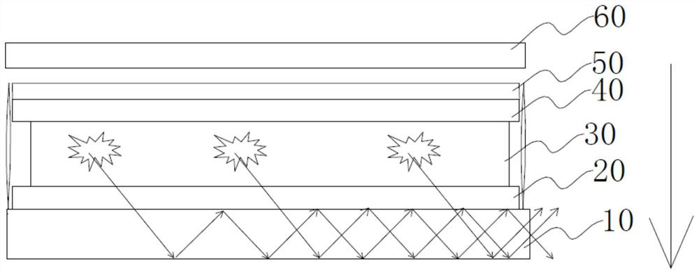
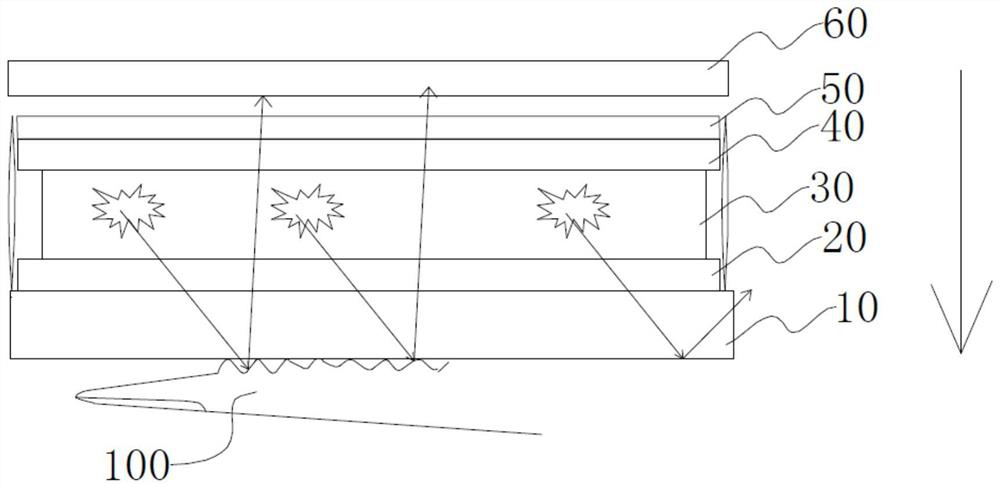
[0059] E.g figure 1 with figure 2 As shown, the OLED fingerprint identification device includes from bottom to top: a substrate 10, a first electrode 20, an organic functional layer 30, a second electrode 40, a package cover 50 and a receiver 60; the direction of the arrow in the figure is the direction of light output, The light-emitting surface of the OLED fingerprint recognition device in this embodiment is set on the bottom surface, and it is a bottom-surface light-emitting fingerprint recognition device. Therefore, the second electrode 40 in this embodiment is a reflective electrode, and the first electrode 20 is a basic electrode.

[0060] Such as figure 1 As shown, in the state of the bare screen, most of the light is sealed in the substrate 10, and only a small amount of light leaks from the side of the substrate 10; figure 2 As shown, after the finger 100 is covered, the finger 100 changes the light emitting direction, so that a large amount of light is reflected ...

Embodiment 2

[0114] E.g Figure 4 As shown, the OLED fingerprint identification device includes from bottom to top: a receiver 60, a substrate 10, a first electrode 20, an organic functional layer 30, a second electrode 40, and a packaging cover 50; the direction of the arrow in the figure is the direction of light output, The light-emitting surface of the OLED fingerprint recognition device in this embodiment is set on the top surface, and it is a top-surface light-emitting fingerprint recognition device. Therefore, the first electrode 20 in this embodiment is a reflective electrode, and the second electrode 40 is a basic electrode.

[0115] In this embodiment, the first electrode 20 is a metal cathode made of Al (aluminum) with a thickness of 150 nm;

[0116] The organic functional layer includes from bottom to top:

[0117] Electron injection layer: main material LiF (lithium fluoride), thickness 0.8nm;

[0118] Electron transport layer: main material Bphen (4,7-diphenyl-1,10-phenanth...

Embodiment 3

[0129] Embodiment 3: On the basis of Embodiment 2, the thickness of the electron transport layer is changed to 57.2 nm; therefore, the distance H from the reflective electrode to the light-emitting layer is 58 nm.

[0130] Control group 2: OLED fingerprint identification device includes from bottom to top: receiver 60, substrate 10, first electrode 20, organic functional layer 30, second electrode 40, packaging cover 50; OLED fingerprint identification device in this embodiment The light-emitting surface is set on the top surface, which is a top-surface light-emitting fingerprint recognition device. Therefore, the first electrode 20 in the second comparison group is a reflective electrode, and the second electrode 40 is a basic electrode.

[0131] In the second control group, the first electrode 20 is a metal cathode made of Al with a thickness of 150nm; the organic functional layer includes from bottom to top:

[0132] Electron injection layer: main material LiF (lithium fluo...


PUM

PropertyMeasurementUnit
thicknessaaaaaaaaaa
thicknessaaaaaaaaaa
thicknessaaaaaaaaaa

Abstract

The invention discloses an OLED screen body used for a fingerprint recognition device as well as a fingerprint recognition device. The OLED screen body comprises a substrate and a light-emitting partencapsulated on the substrate by virtue of an encapsulation cover plate; the light-emitting part comprises an organic functional layer as well as a reflecting electrode and a base electrode respectively arranged at the two sides of the organic functional layer; the organic functional layer is internally provided with a light-emitting layer and a plurality of organic layers arranged at the two sides of the light-emitting layer; the reflecting electrode is arranged at one side, far away from the light-emitting layer, of a light-exiting surface; and distance between the reflecting electrode and the light-emitting layer meets a set formula. The OLED screen body disclosed by the invention has the advantages that the distance between the reflecting electrode and the light-emitting layer in the OLED screen body is uniquely selected, most lights with fixed wavelength are limited by the substrate or the encapsulation cover plate in a total reflection form or are emergent in a lateral light form, and strength and accuracy of a received signal are enhanced, so that recognition sensitivity of the fingerprint recognition device is improved.

Description

technical field [0001] The present disclosure generally relates to the technical field of fingerprint identification, and in particular to an OLED screen for a fingerprint identification device and a fingerprint identification device. Background technique [0002] In recent years, with the development of display lighting technology, mobile products with biometric identification functions have gradually developed, especially fingerprint identification technology, which has been widely used in mobile phone security and various enterprise security equipment. The core is also the fingerprint identification technology in the display area. At present, there are already many fingerprint identification devices designed for optical fingerprint identification in a series of ways. For example, as shown in the content published in the Chinese invention patent with the application number 201510096644.X; in this patent, a grating and an external LED light source are used to make a paralle...

Claims


Application Information

Patent Timeline
Patent Type & Authority Patents(China)
IPC IPC(8): H01L51/52G06K9/00
Inventor 于倩倩李育豪鲁天星朱映光谢静郭立雪
Owner GUAN YEOLIGHT TECH CO LTD
Why Eureka
Try Eureka