
Led drive circuit
An LED drive and circuit technology, applied in circuit layout, lamp circuit layout, electric light source, etc., can solve the problems of low rated power, low rated voltage, application limitations, etc.
- Summary
- Abstract
- Description
- Claims
- Application Information
AI Technical Summary
Problems solved by technology
Method used
Image

Examples
no. 1 example
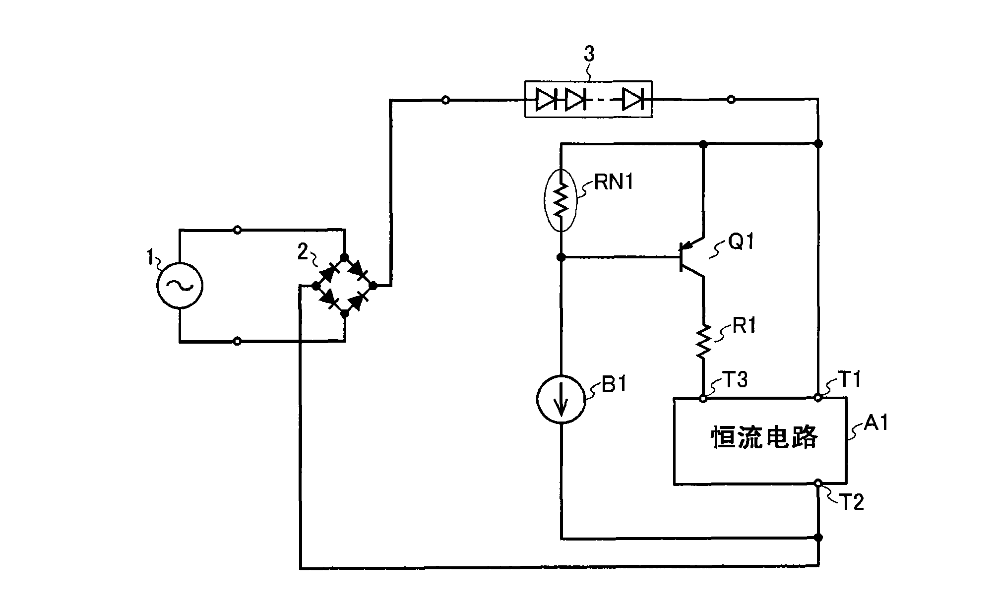
[0050] figure 1 The configuration of the LED driving circuit according to the first embodiment of the present invention is shown in . figure 1 The LED driving circuit of this embodiment shown includes: a bridge diode 2; constant current circuits A1 and B1; a PNP transistor Q1; a resistor R1; and a negative temperature coefficient resistor RN1 such as an NTC thermistor (hereinafter referred to as "NTC resistor RN1").
[0051] The input end of the bridge diode 2 is connected to the commercial AC100V power supply 1 , and one output end of the bridge diode 2 is connected to the anode of the LED module 3 . The constant current terminal T1 of the constant current circuit A1 is connected to the cathode of the LED module 3 , and the constant current terminal T2 of the constant current circuit A1 is connected to the other output end of the bridge diode 2 . The emitter of the PNP transistor Q1 is connected to the cathode of the LED module 3 , and the collector of the PNP transistor ...
no. 2 example
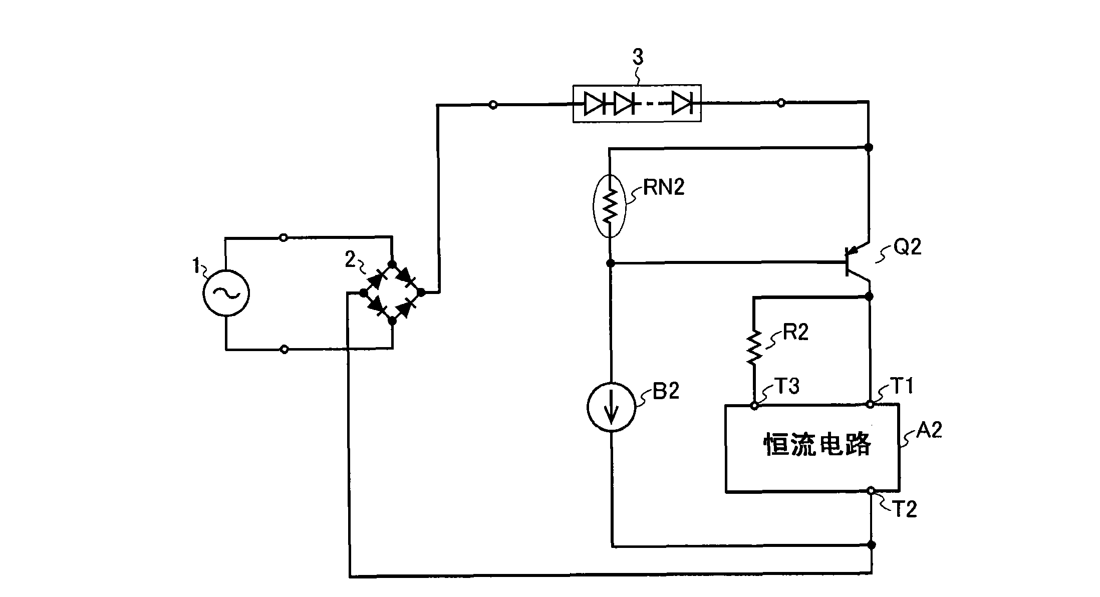
[0058] figure 2 The configuration of the LED driving circuit according to the second embodiment of the present invention is shown in . figure 2 The LED driving circuit of this embodiment shown is provided with: a bridge diode 2; constant current circuits A2 and B2; a PNP transistor Q2; a resistor R2; and a negative temperature coefficient resistor (hereinafter referred to as "NTC resistor") RN2.
[0059]The input end of the bridge diode 2 is connected to the commercial AC100V power supply 1 , and one output end of the bridge diode 2 is connected to the anode of the LED module 3 . The cathode of the LED module 3 is connected to the emitter of the PNP transistor Q2. The constant current terminal T1 of the constant current circuit A2 is connected to the collector of the PNP transistor Q2 , and the constant current terminal T2 of the constant current circuit A2 is connected to the other output terminal of the bridge diode 2 . Also, the collector of the PNP transistor Q2 is con...
no. 3 example
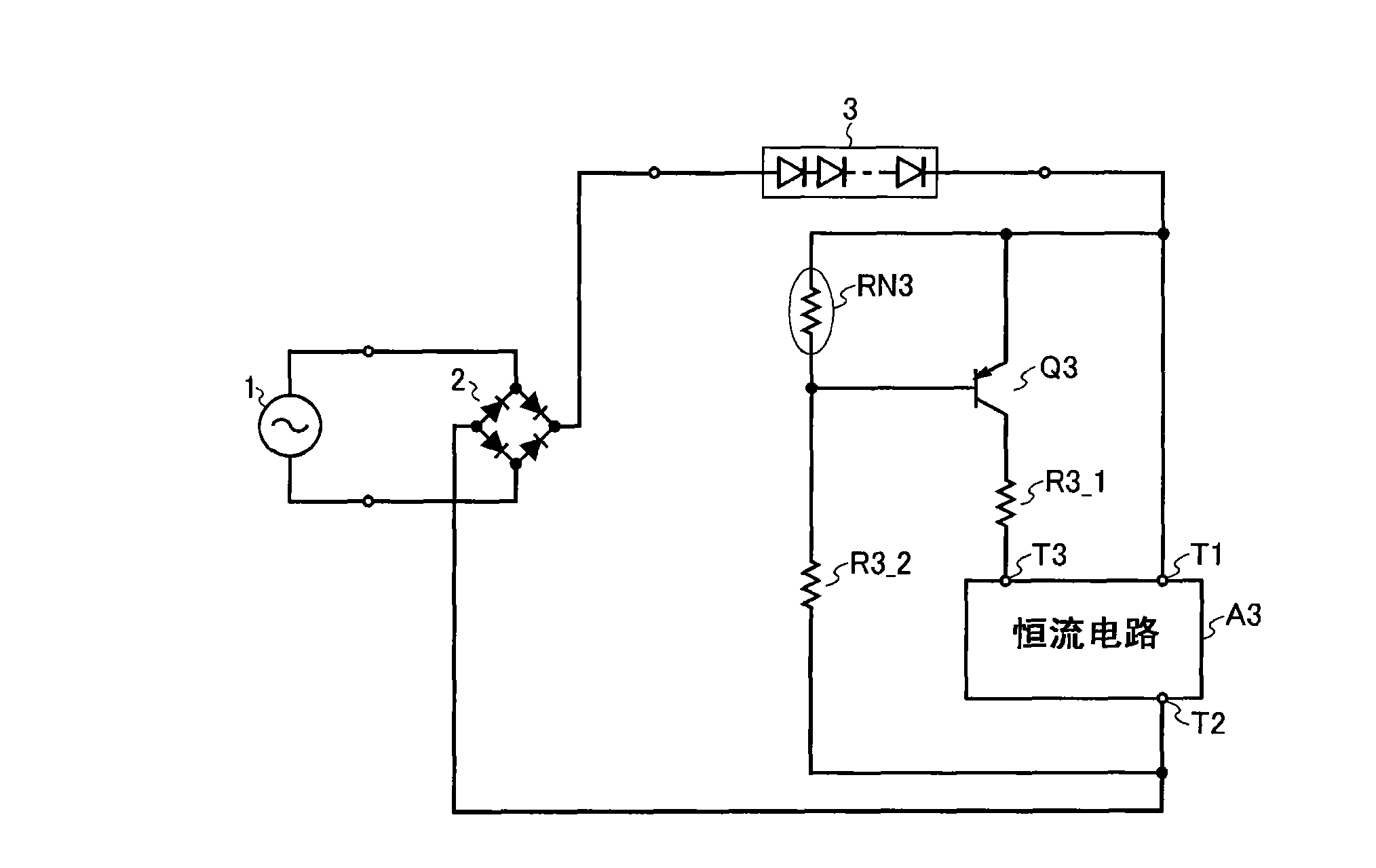
[0065] image 3 The configuration of the LED driving circuit according to the third embodiment of the present invention is shown in . image 3 The LED driving circuit shown in this embodiment includes: a bridge diode 2; a constant current circuit A3; a PNP transistor Q3; resistors R3_1 and R3_2; and a negative temperature coefficient resistor (hereinafter referred to as "NTC resistor") RN3.
[0066] The input end of the bridge diode 2 is connected to the commercial AC100V power supply 1 , and one output end of the bridge diode 2 is connected to the anode of the LED module 3 . The constant current terminal T1 of the constant current circuit A3 is connected to the cathode of the LED module 3 , and the constant current terminal T2 of the constant current circuit A3 is connected to the other output end of the bridge diode 2 . Moreover, the emitter of the PNP transistor Q3 is connected to the cathode of the LED module 3 , and the collector of the PNP transistor Q3 is connected to ...
PUM
 Abstract
Description
Claims
Application Information