Rotating chain plate bottle-standing type straightener

A bottle unscrambler and chain plate technology, applied in the direction of conveyor objects, transportation and packaging, can solve the problems affecting the operation efficiency of the unscrambler line, safety and insecurity, and high labor intensity, so as to improve labor productivity and economic benefits. The effect of saving energy consumption and manpower, and fast working speed

Active Publication Date: 2010-02-17
周飞
1 Cites 10 Cited by

AI-Extracted Technical Summary

Problems solved by technology

At present, there is no automatic bottle unscrambling equipment for glass bottles such as beer at home and abroad. Many links on the assembly line are still manually operated, resulting in high bottle damage rate, low efficiency, high labor intensity, poor working environment, and no guarantee of safety. Beer, etc. Technical problems that enterprises cannot solve for a long time
Adopt the bottle turner of semi-closed structure in the linear type bottle unscrambler that CN200981813Y proposes, set the screw hole of a large pitch in this bottle turner, the length, width and height of this screw hole are equal to the length, width and height of the bottle to be sorted , there are many technical problems in this structure. First, eac...

Abstract

The invention relates to a rotating chain plate bottle-standing type straightener which comprises a transmission motor, a gearbox, a transmission wheel and transmission belts, wherein two rotating chain plate transmission chains are arranged in the middle of the two bottle outlet transmission belts, and the middle part between the two rotating chain plate transmission chains is provided with a bottle support plate with both inclined surfaces; guide rails changed along the height of the inclined surfaces are arranged on both inclined surfaces of the bottle support plate, and a rotating chain plate which is in movable contact with the guide rails is rotated to the vertical position from the horizontal position along the trend of the guide rails; a drop bottle straightening device which leadsa glass bottle to accurately drop in a bottle positioning machine is arranged above the head end of the rotating chain plate; and the outer sides of the bottle outlet transmission belts are providedwith bottle-standing blocking plates which lead the glass bottle to stand. The invention solves the problem of slow standing of the glass bottle on the flow line in running, and has no bottle breakageand blockage by adopting the rotating chain plate transmission chains as the transmission belts, high continuous operation speed and efficiency, and space, energy resource and man power saving, thereby greatly improving the labour productivity and economic benefits.

Application Domain

Technology Topic

Image

  • Rotating chain plate bottle-standing type straightener
  • Rotating chain plate bottle-standing type straightener
  • Rotating chain plate bottle-standing type straightener

Examples

  • Experimental program(1)

Example Embodiment

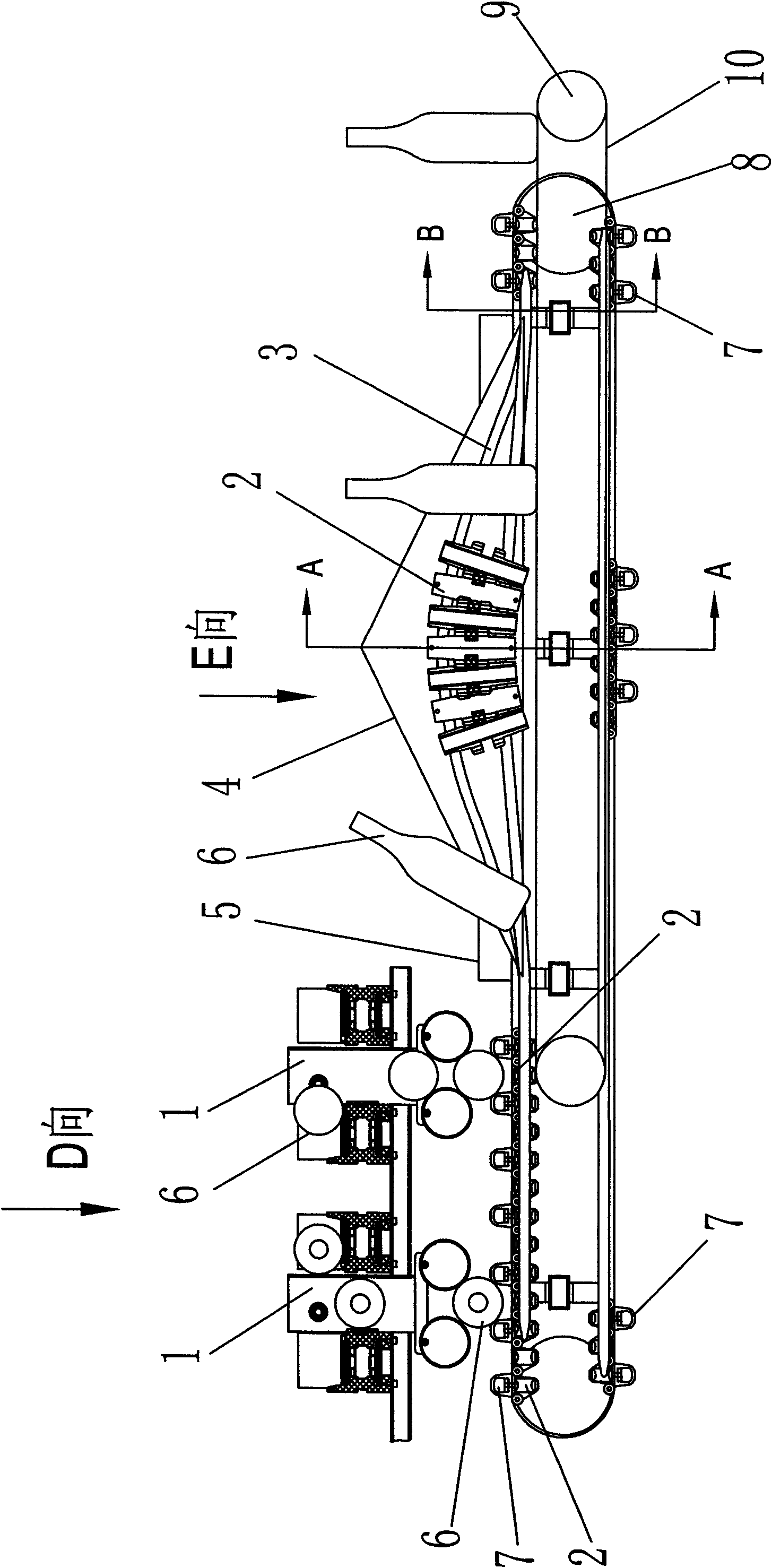
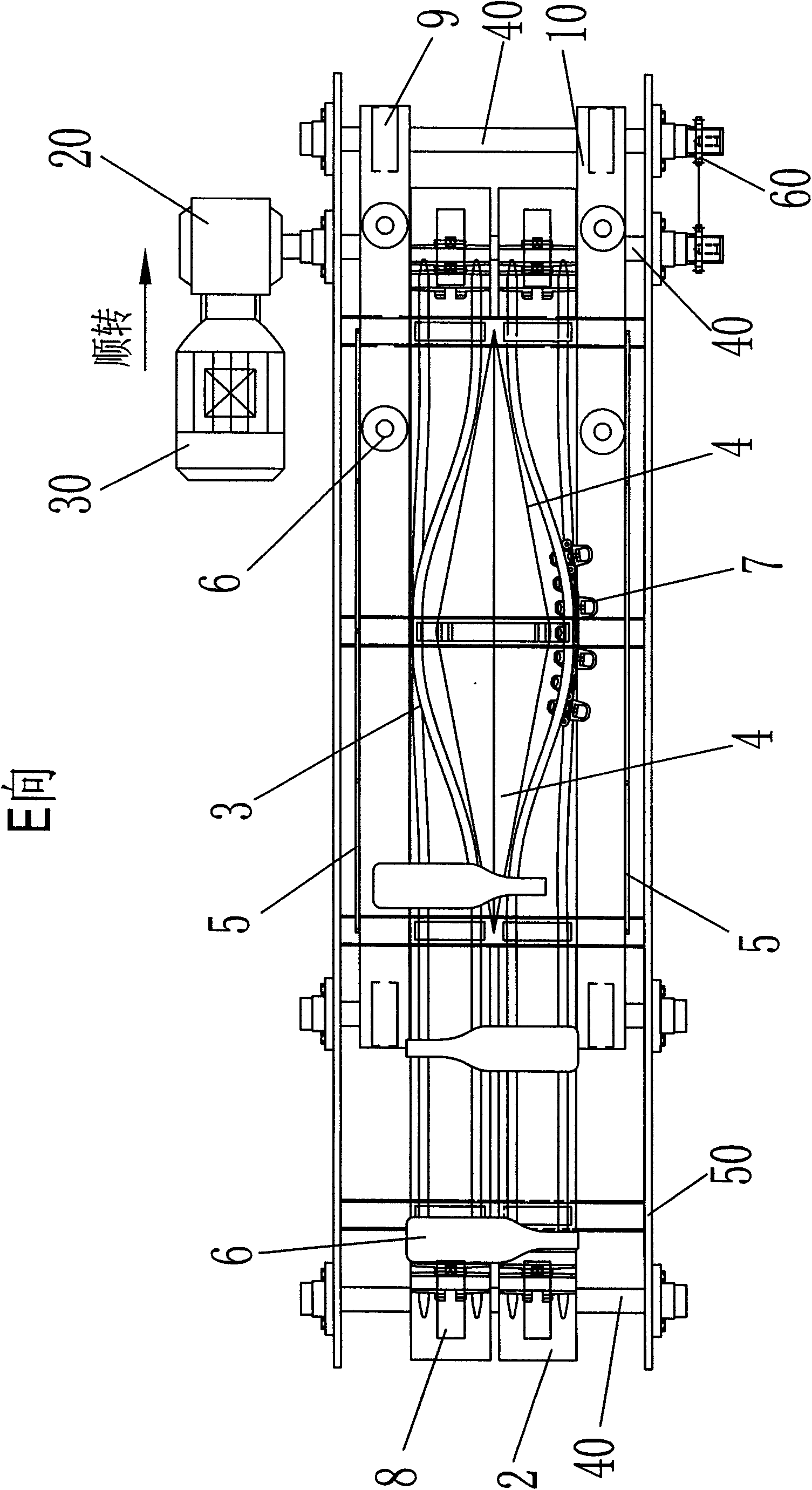
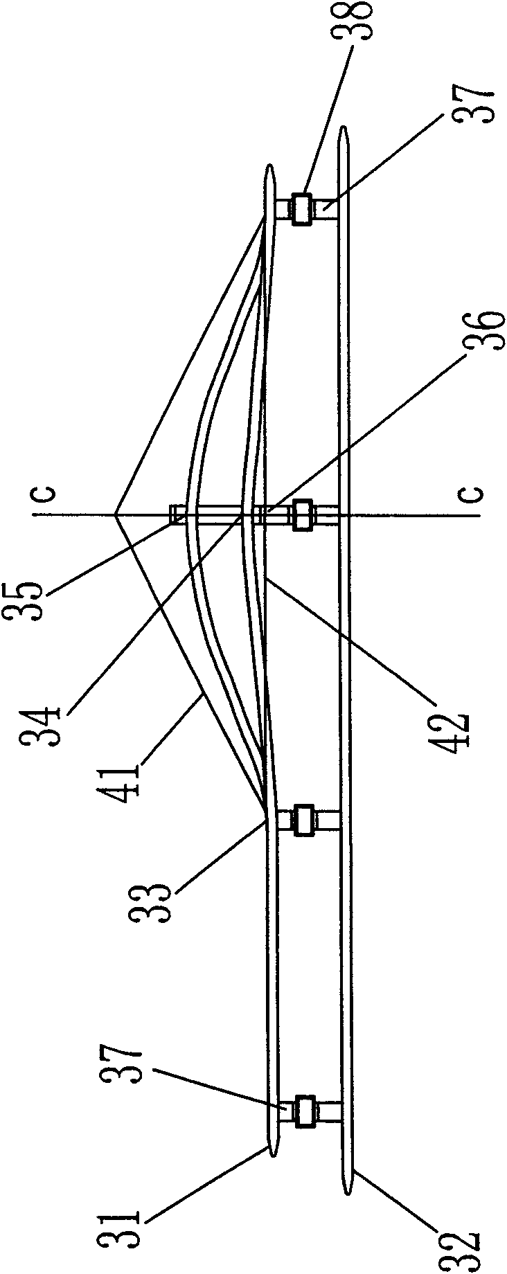
[0015] see figure 1 and figure 2 As shown, the basic structure of the present invention includes a bottle drop straightener 1 arranged between the conveyor belts on the upper layer, a rotating chain plate 2 disposed between the two conveyor belts on this layer, and a middle part between the two rotating chain plates. The two sides of the bottle holding plate 4 are inclined surfaces; on each inclined surface of the bottle holding plate, a guide rail 3 that changes in height along the inclined plane is arranged, and a rotating chain plate 2 that can slide along the guide rail is laid on the guide rail 3 The transmission chain formed in series, the main transmission wheel 8 of the transmission chain is driven by the motor 30 through the transmission 20 to drive the transmission chain to run. On the outside of the transmission chain of the rotating chain plate 2, a parallel bottle conveying belt 10 is arranged, and the conveying belt 10 is slightly lower than the rotating chain plate transmission chain. The bottle conveyor belt 10 is driven by the drive wheel 9, and the drive wheel 9 obtains the rotational force from the roller shaft 40 by the sprocket 60, and makes the bottle conveyor belt 10 and the rotating chain plate 2 run in the same direction. The roller shaft 40 and the drive wheel 9 and the sprocket 60 is supported by the support frame 50 .
[0016] like figure 1 As shown, an elastic clamping block 7 is arranged on the rotating chain plate 2 spaced from a panel, and the glass bottle 6 transmitted from the upper conveyor belt can accurately fall on the rotating chain plate 2 after being straightened by the bottle drop straightener 1 , between the two elastic clamping blocks 7 and carried forward by the transmission chain. like figure 2 As shown in the figure, the glass bottle 6 falling between the elastic clips 7 on the rotating chain plate 2 is transmitted to the tip of the protrusion of the bottle holding plate 4. Due to the different orientations of the bottle mouth and the bottle bottom, under the action of the movement speed and gravity, The bottom of the bottle with the bottle mouth facing forward stands the bottle to the back, and the bottle is turned into the rear rotating chain plate. To the role of the bottle.
[0017] FIG. 3 shows the structure of the guide rail and the bottle holding plate. The bottle holding plate 4 is formed by the intersection of the left and right symmetrical triangular vertices to form a left and right symmetrical slope. The left and right symmetrical slope 41 is arranged on the middle horizontal line 42 between the upward guide rails 31 above. The upward guide rail 31 and the downward guide rail 32 of the guide rail 3 are connected and supported by the guide rail bracket 37 , the guide rail middle frame 36 and the guide beam 38 . for parallel settings, such as Figure 3b shown. When approaching the slopes 41 on both sides of the bottle holding plate 4, the two guide rails 31 gradually climb up to the highest points 35 and 34 of the guide rail middle frame 36 along the height change of the slope, and the upper and lower guide rails are in a vertical state, such as Figure 3c As shown, the two sides of the guide rail bracket 37 are respectively fixed vertically with the guide rail middle frame 36, the upper and lower rails of the upward guide rail 31 are respectively suspended between the upper support point 35 and the lower support point 34 on the same side, and the upward guide rail bracket 37 It is vertically fixed to the two sides of the guide rail middle frame 36 respectively. The guide rail bracket 37 of the downward guide rail 32 is fixed in parallel with the bottom surface of the guide rail beam 38, and the downward guide rail 32 is suspended between the two parallel support points 35 and 34 of the guide rail 37, so that the upward guide rail 31 is suspended. The guide rail 32 is suspended vertically on the upper and lower support points 35 and 34 of the guide rail bracket, and the downward guide rail 32 is suspended in parallel between the two parallel support points 35 and 34 of the guide bracket 37 .
[0018] FIG. 4 shows the structure diagram of the rotary link plate 2. The rotary link plate 2 consists of a panel 29, circular arc surface runners 28 provided on both ends of the bottom surface of the panel, upper and lower circular holes 27 provided on the left side of the panel 29, and The conical hole tube 26 in the middle of the right concave surface forms a basic unit. like Figure 4a The tapered hole of the tapered hole pipe 26 shown is composed of double tapered holes with the small ports of the upper and lower tapered holes facing each other in the middle and the large ports facing outward respectively. like Figure 4b and Figure 4c The arc slide grooves 28 at both ends of the bottom surface of the panel 29 are rectangular grooves with two slots parallel to the panel 29. The inner bottom surface 22, the inner left surface 24 and the inner right surface 23 of the rectangular groove are arc surfaces. like Figure 4d The transmission chain composed of several rotating chain plates 2 shown is composed of chain plate pins 21 passing through the upper and lower round holes 27 on the left side of the rotating chain plate panel 29 and the tapered hole tube 26 in the middle of the right middle of the other rotating chain plate panel. When the chain plate pin 21 is inserted into the tapered hole tube 26, the upper and lower ports of the tapered hole tube 26 are large, the middle hole is small, and the outer end face of the round hole foot 27 and the end face of the inner recess are each chamfered 25, which makes the rotating chain plate 2 rotate. It is flexible and can be rotated in any direction, so that the transmission chain combined in series can be twisted and bent arbitrarily in 360 degrees, for plane meandering transmission or circular transmission, or spiral up or down along the central axis.
[0019] The bottle locator is composed of an elastic clamping block 7 which is connected in series to the panel 29 of a rotating chain plate 2 in series on the transmission chain. The elastic clamping block 7 is a hollow rectangular rubber tube.
[0020] The bottle drop straightener 1 shown in FIG. 5 includes a bottle drop plate 13 arranged between the upper conveying rails, a bottle drop buffer block 11 arranged on the upper part of the bottle drop plate 13 , and a bottle drop bracket arranged at the lower part of the bottle drop plate 13 14. The straightening cylinder shaft 15 and the elastic straightening roller 16 hanging outside the straightening cylinder shaft 15 are hung under the bottle-dropping bracket 14 . The elastic straightening drum 16 is generally made of steel and covered with rubber. The bottle drop plate 13 is fixed between the upper conveying rails by the fixed horizontal bars 12. When they collide, that is, they fall between the two elastic rollers 16. Since the two elastic rollers 16 are suspended on the periphery of the cylindrical shaft 15, they are always in an eccentric sliding state. Can form a channel for the bottle to fall horizontally, such as Figure 5b and Figure 5c shown. Moreover, in the design, the width between the two straightening cylinder shafts 15 is equal to the interval width of the elastic clips 7 arranged on the rotating chain plate 2 and corresponds to the upper and lower sides, so that each falling glass bottle can be accurately dropped. into the clamping groove between the elastic clamping blocks 7, and is transported forward by the rotating chain plate 2.
[0021] like figure 1 , 2 and Figure 8 As shown, the glass bottles 6 coming out of the upper bedding track can be a conveyor belt with the bottle mouth facing forward, or a conveyor belt with the bottle bottom facing forward, all of which are common. When the glass bottle 6 arrives, it is impacted by the buffer block 11 and falls into the clamping groove between the elastic clamping blocks 7 on the rotating chain plate 2, and is transmitted by the transmission chain to the front protruding tip 33 of the bottle holding plate 4. On the 33, according to the weight difference between the bottle mouth and the bottle bottom, they are respectively pulled to the left and right guide rails 3 to automatically complete the left and right bottle separation. To achieve the purpose of vertical bottles.
[0022] see figure 1 , Image 6 and Figure 7 As shown, the glass bottle 6 is transported by the elastic clip groove on the rotating chain plate 2 to the slope along the bottle holding plate 4 and continues to move forward, and the glass bottle 6 is gradually turned upright from the horizontal position according to the slope height, such as Image 6As shown, in the A-A position, since the rotating chain plate 2 is turned into an upright state on the upward transmission chain, the glass bottle 6 clamped by the elastic clamping block 7 automatically falls into the conveyor belt 10 under the action of gravity under the vertical bottle baffle 5. Under the protection, it is sent out again, that is, into the Figure 7 In the state shown, the upward rotating chain plate 2 is restored from the vertical state to the horizontal state, that is, the upward transmission chain and the downward transmission chain run in anti-parallel. exist Image 6 , Figure 7 The downward part of the bottle conveyor belt 10 is omitted, all the downward conveyor belts pass through the main driving wheel 8 and the driven wheel 9 respectively and then return upward and return to the bottom of the bottle drop straightener 1, repeating the next cycle.

PUM

no PUM

Description & Claims & Application Information

We can also present the details of the Description, Claims and Application information to help users get a comprehensive understanding of the technical details of the patent, such as background art, summary of invention, brief description of drawings, description of embodiments, and other original content. On the other hand, users can also determine the specific scope of protection of the technology through the list of claims; as well as understand the changes in the life cycle of the technology with the presentation of the patent timeline. Login to view more.

Similar technology patents

Cutter head for efficiently milling steel rail

PendingCN110258214AFast workEliminate diseaseRailway track constructionCommon diseaseEngineering
Owner:BEIJING TUOBOER TRACK MAINTENANCE TECH CO LTD

Vehicle-mounted snow removal mechanism

InactiveCN106149613AImprove snow removal efficiencyFast workSnow cleaningIn vehicleBroom
Owner:哈尔滨通用液压机械制造有限公司

Emergency rescue vehicle control method and device and emergency rescue vehicle

ActiveCN112299328AImprove efficiencyFast workLifting devicesCranesRescue vehicleEmergency rescue
Owner:JIANGSU XCMG CONSTR MASCH RES INST LTD

Automatic sand pit trowelling device for standing long jump

InactiveCN114404922AFast workImprove smoothing effectSki bindingsWater-skiingEngineeringStructural engineering
Owner:ZHENGZHOU UNIV OF IND TECH

Classification and recommendation of technical efficacy words

  • Fast work
  • Improve efficiency

Antirust oil and preparation method thereof

InactiveCN107653045AFast workGood anti-rust effectLubricant compositionCo solventAntioxidant
Owner:上海有道新能源技术有限公司 +1

Railway turnout transport cart

ActiveCN107130480ALong distance transportFast workRailway track constructionCartEngineering
Owner:ZHUZHOU TIMES ELECTRONICS TECH CO LTD

Automatic spot welding machine

Owner:SUZHOU NIPPO AUTOMATION TECH

Deodorization foam and foam deodorization system

InactiveCN107441918AFast workThoroughly deodorizedDispersed particle separationDeodrantsChemistryDecomposition
Owner:福州艾美林环保科技有限公司
Why Eureka
Try Eureka