
Cross axle-type universal coupling

A universal coupling and cross shaft technology, used in couplings, elastic couplings, mechanical equipment, etc., can solve the problems of uncertain clearance, affecting assembly accuracy, reducing the service life of couplings, etc., to achieve assembly and disassembly. Easy, reasonable structure design, the effect of improving the service life

Inactive Publication Date: 2010-02-17
HENAN SANWEI HEAVY IND
View PDF0 Cites 2 Cited by
  • Summary
  • Abstract
  • Description
  • Claims
  • Application Information

AI Technical Summary

Problems solved by technology

Most of the traditional cross-shaft universal joints adopt the overall yoke structure to improve the reliability and strength of the yoke. The yoke hole and the bearing sleeve adopt interference fit, and there is a certain amount of interference between the two. It leads to difficult installation and easy to scratch the joint surface, which affects the assembly accuracy and changes the use status, and reduces the service life of the coupling; due to the large load on site, frequent impacts, frequent maintenance, and the existence of interference, the bearing sleeve is not easy to disassemble. Rear related parts are easy to damage, increasing maintenance costs
The roller bearings of traditional cross-shaft universal joints mostly use a fixed rib structure to guide the roller end faces. Due to machining errors, the clearance is not fixed, so the rollers cannot be accurately guided to rotate.

Method used


Image

  • Cross axle-type universal coupling
  • Cross axle-type universal coupling
  • Cross axle-type universal coupling

Examples


Embodiment Construction

[0019] The present invention will be described in further detail below in conjunction with the accompanying drawings and embodiments.

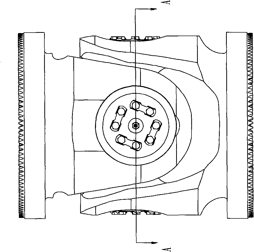
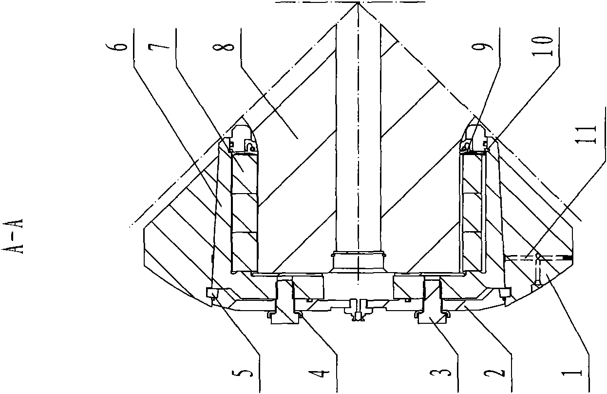
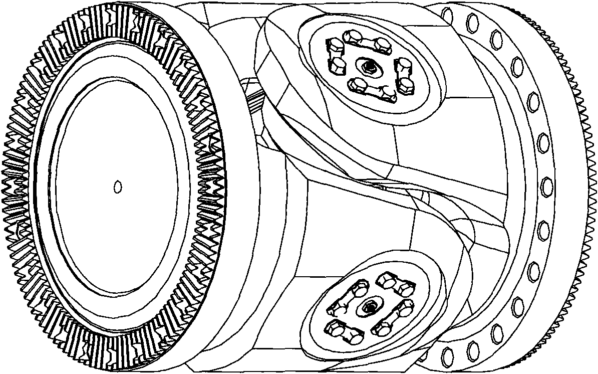
[0020] like figure 1 , 2 , shown in 3: the cross-shaft universal joint of the present invention, which is composed of a yoke 1, an end cover 2, an annular retaining ring 5, a bearing sleeve 6, a cross shaft 8, a roller bearing 7 and a flat retaining ring 10 components, the journal of the cross shaft 8 is installed in the shaft hole of the yoke 1, the root of the journal of the cross shaft is provided with a flat retaining ring 10, the roller bearing 7 is installed on the journal of the cross shaft, and the shaft of the yoke 1 A bearing sleeve 6 is assembled on the inner wall of the hole, and the right end surface of the bearing sleeve is pressed against the flat retaining ring 10, so that the roller bearing is located between the bearing sleeve and the flat retaining ring, and a wave is arranged between the roller bearing 7 and the flat retai...


PUM


Abstract

The invention discloses a cross axle-type universal coupling which consists of a jaw, an end cover, an annular check ring, a bearing housing, a cross axle, a roller bearing and a loose rib. The axle journal of the cross axle is arranged in an axle hole of the jaw; the root of the axle journal of the cross axle is provided with the loose rib; the roller bearing is arranged on the axle journal of the cross axle; the inner wall of the axle hole of the jaw is provided with the bearing housing; the right end surface of the bearing housing is pressed on the loose rib; a wave spring is arranged between the roller bearing and the loose rib; the outer wall of the bearing housing has a certain conicity and cooperates with the axle hole with the conicity of the jaw; at the position of the left end surface of the bearing housing, the inside diameter of the axle hole of the jaw is provided with an annular slot; the annular check ring cooperating with the annular slot is arranged in the annular slot; the conicity cooperating with the annular check ring is set on the end cover; a bolt is utilized to connect the end cover and the bearing housing, and the annular check ring is tightly pressed on the bearing housing; and a certain clearance is arranged between the end cover and the left end surface of the bearing housing, thereby achieving easy assembly and detaching, reliable use and long service life.

Description

technical field [0001] The invention belongs to the technical field of shaft couplings, in particular to a cross-shaft universal joint. Background technique [0002] At present, cross-shaft universal couplings have been widely used in mining and metallurgical industries to provide power transmission, and they must bear huge torque and impact loads during use. Most of the traditional cross-shaft universal joints adopt the overall yoke structure to improve the reliability and strength of the yoke. The yoke hole and the bearing sleeve adopt interference fit, and there is a certain amount of interference between the two. It leads to difficult installation and easy to scratch the joint surface, which affects the assembly accuracy and changes the use status, and reduces the service life of the coupling; due to the large load on site, frequent impacts, frequent maintenance, and the existence of interference, the bearing sleeve is not easy to disassemble. Rear related components ar...

Claims


Application Information

Patent Timeline
Patent Type & Authority Applications(China)
IPC IPC(8): F16D3/26
Inventor 刘乐民陈岩松
Owner HENAN SANWEI HEAVY IND
Learn More