Photoelectric sensor for position of sun
A photoelectric sensor and sun position technology, applied in the sensor field, can solve the problems of low sensor accuracy and small tracking range, and achieve the effects of convenient use, low cost and simple structure
- Summary
- Abstract
- Description
- Claims
- Application Information
AI Technical Summary
Problems solved by technology
Method used
Image

Examples
Embodiment Construction
[0012] The present invention will be further described in detail below in conjunction with the embodiments and accompanying drawings.
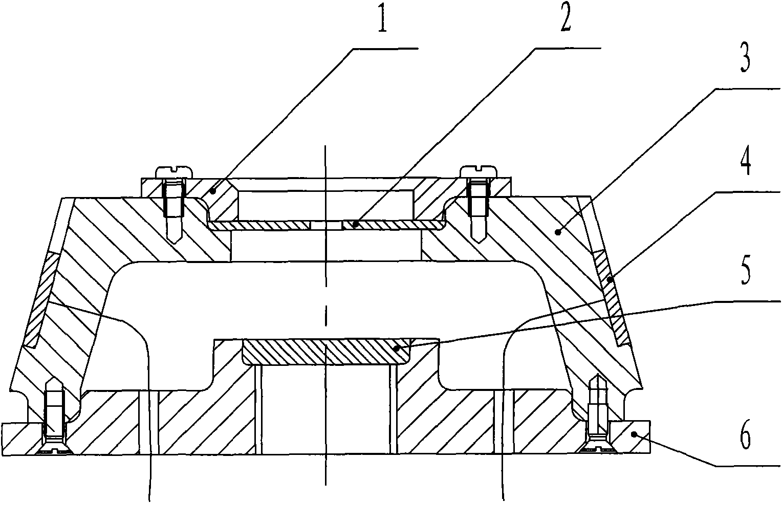
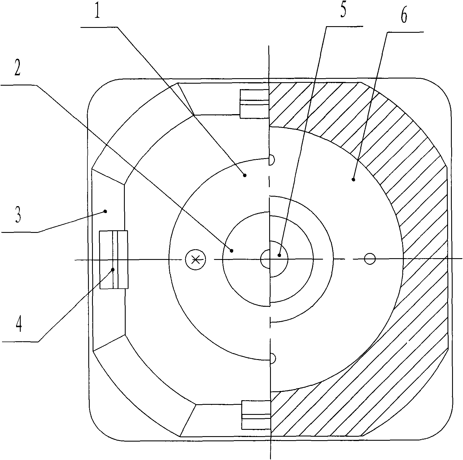
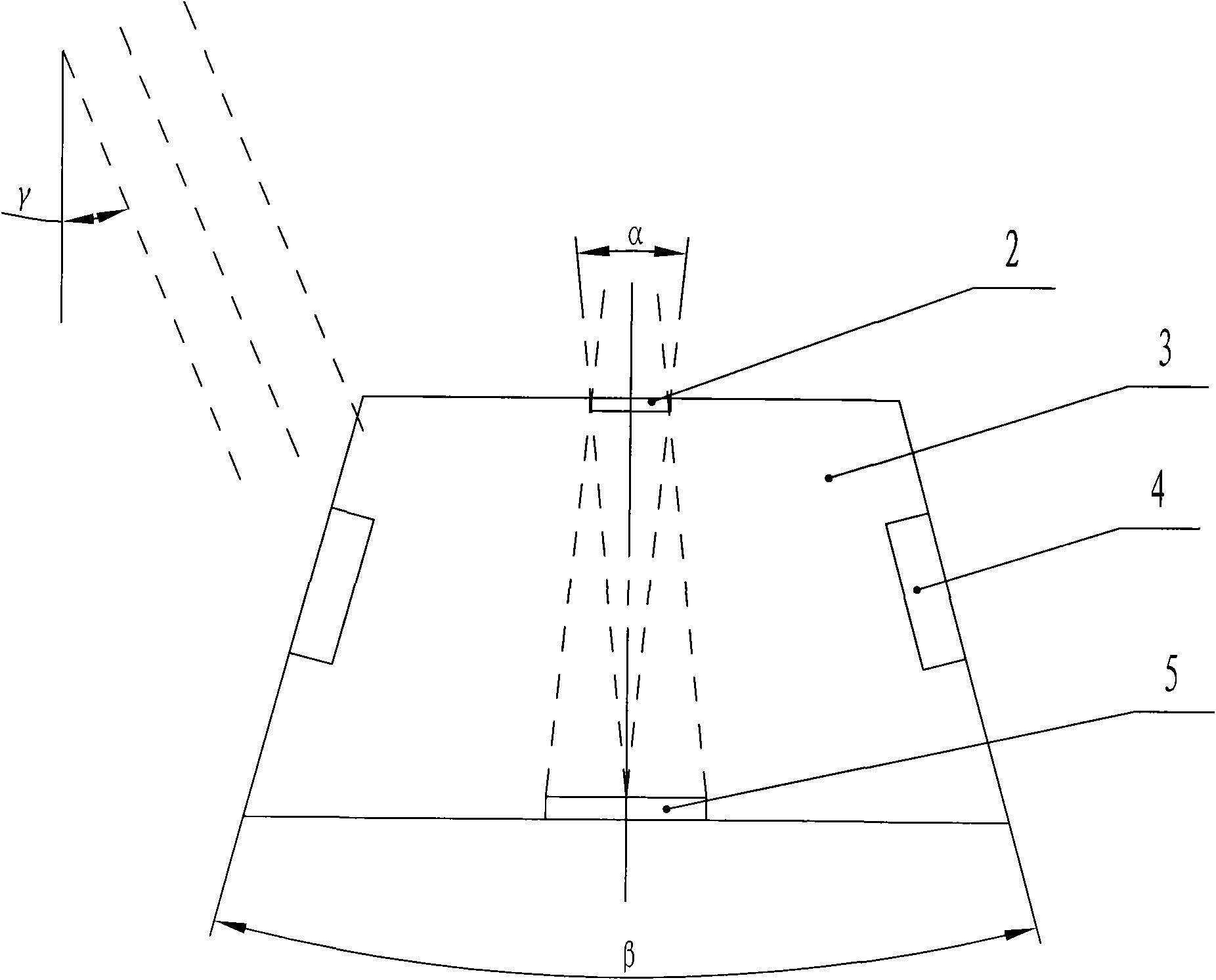
[0013] The sun position photoelectric sensor provided by the invention has a structure such as Figure 1 to Figure 4 As shown: there is an accurate tracking component inside, and a rough tracking component outside; the precise tracking component is composed of a light aperture 2 and a four-quadrant silicon photocell 5, the four-quadrant silicon photocell is placed on the base 6 of the sensor, and the light aperture The optical class hole is located directly above the four-quadrant silicon photocell, and the center of the optical class hole and the origin of the four-quadrant silicon photocell are located on the central axis of the sensor; the rough tracking component is composed of four ordinary silicon photocells 4, which are evenly distributed on the sensor. On the outside of the inclined wall 3 of the sensor.
[0014] The distance between ...
PUM
 Abstract
Description
Claims
Application Information
 - R&D
- Intellectual Property
- Life Sciences
- Materials
- Tech Scout
- Unparalleled Data Quality
- Higher Quality Content
- 60% Fewer Hallucinations
Browse by: Latest US Patents, China's latest patents, Technical Efficacy Thesaurus, Application Domain, Technology Topic, Popular Technical Reports.
© 2025 PatSnap. All rights reserved.Legal|Privacy policy|Modern Slavery Act Transparency Statement|Sitemap|About US| Contact US: help@patsnap.com