Optical detection equipment and method

A technology of optical detection and equipment, applied in the direction of testing optical properties, material analysis through optical means, measuring devices, etc., can solve problems such as affecting results, uneven coating, and difficult quality control

Inactive Publication Date: 2010-02-17
DELTA ELECTRONICS INC
View PDF0 Cites 17 Cited by
  • Summary
  • Abstract
  • Description
  • Claims
  • Application Information

AI Technical Summary

Problems solved by technology

[0004] 1. Quality control is not easy: because it cannot be detected one by one by manual sampling method, and it must be judged visually by people under different angles and different intensity light sources. Missed inspections that can only be detected after missed inspections
[0005] 2. Unable to conduct statistical process analysis: The existing technology cannot effectively record the characteristics and classifica

Method used


Image

  • Optical detection equipment and method
  • Optical detection equipment and method
  • Optical detection equipment and method

Examples


Embodiment Construction

[0065] The technical means of the present invention will be described in detail as follows. It is believed that the purpose, characteristics and characteristics of the present invention should be able to obtain a deep and specific understanding. However, the following examples and illustrations are only provided for reference and illustration, and are not used to describe the present invention. be restricted.

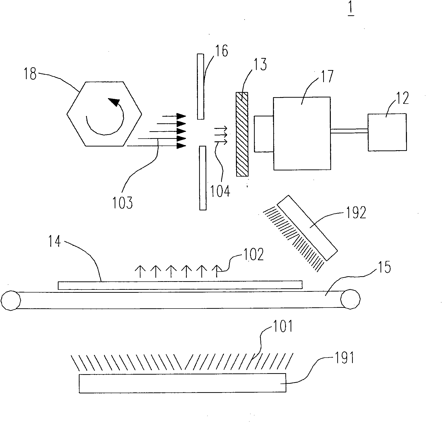
[0066] See first figure 1 , which is a schematic diagram of the configured optical detection device 1 of the first embodiment of the optical detection device of the present invention. exist figure 1 Among them, an optical detection device 1 includes a first light source 191 , a reflective element 18 , a carrier element 15 , a mask element 16 , an optical filter element 13 , an array receiving sensor element 17 and an image acquisition element 12 . In order to achieve the purpose of optical detection, a test object 14 is placed on the carrier element 15, the first ligh...


PUM

PropertyMeasurementUnit
Wavelengthaaaaaaaaaa

Abstract

The invention relates to optical detection equipment, which can improve the accuracy and the effect of the defect detection of a substrate, and further improve the process yield and reduce the production cost by using a projective image formed by light rays with multiple visual angles and different wavelengths. The optical detection equipment comprises a light source, a reflective element and an image acquisition element, wherein the light source projects the light rays to an object to be detected; the reflective element is provided with at least two reflective surfaces for reflecting the light rays passing through the object to be detected; and the image acquisition element receives the reflected light rays to form the projective image.

Description

technical field [0001] The invention relates to an optical detection device and method, in particular to an optical detection device and method for detecting uneven color defects of color filters. Background technique [0002] The uneven color of the color filter is caused by visual perception of different degrees of color difference under the same light source and the same background color. Poor coating causes light to be refracted at different angles and therefore responds differently to color from different viewing angles. [0003] At present, the method of artificial sampling inspection is still widely used in the field for the detection of uneven color, which has the following disadvantages: [0004] 1. Quality control is not easy: because it cannot be tested one by one by manual sampling inspection, and it must be judged visually by people under different angles and different intensity light sources. The missed detection can only be detected after the missed detectio...

Claims


Application Information

Patent Timeline
IPC IPC(8): G01N21/958G01M11/02
Inventor 张仁明许贸雄陈诗涌李俞玺沈家麟林瑞堉
Owner DELTA ELECTRONICS INC
Why Eureka
Try Eureka