Backlight scanning control method and device of 3D liquid crystal television

A technology of LCD TV and backlight scanning, applied in electrical components, instruments, static indicators, etc., can solve the problem of not increasing the field frequency, and achieve the effect of improving contrast, solving crosstalk between left and right pictures, and good 3D display effect

Active Publication Date: 2010-02-17
HISENSE VISUAL TECH CO LTD
View PDF0 Cites 55 Cited by
  • Summary
  • Abstract
  • Description
  • Claims
  • Application Information

AI Technical Summary

Problems solved by technology

However, from image 3 It can also be seen in , this solution must increase the field frequency, and increase the field frequency from 120Hz to 240Hz, so that the black field can be inserted
[0008] At present, there is no technical solution in the prior art to achieve 3D display without crosstalk between left and right eye images without increasing the field frequency, that is, on the basis of maintaining a field frequency of 120 Hz

Method used


Image

  • Backlight scanning control method and device of 3D liquid crystal television
  • Backlight scanning control method and device of 3D liquid crystal television
  • Backlight scanning control method and device of 3D liquid crystal television

Examples


Embodiment 1

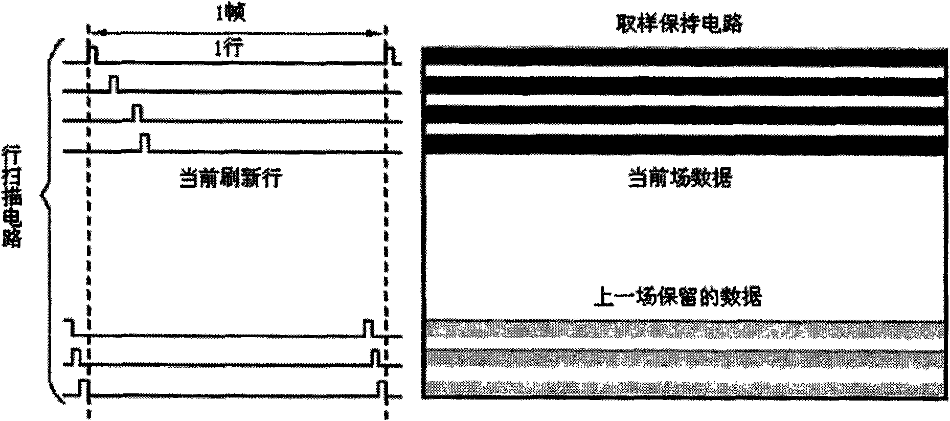
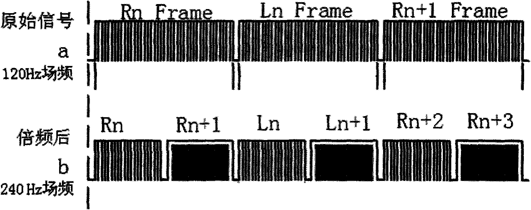
[0028] Figure 4A It is a schematic timing diagram of the backlight scanning control method according to Embodiment 1 of the present invention. Figure 4A The middle a is a signal sequence diagram showing that the left and right eye signals alternate. In the embodiment of the present invention, the image data of the left and right eyes are alternately refreshed and displayed at a field frequency of 120 Hz. The LCD screen and the backlight unit are divided into four areas A, B, C, and D, which are refreshed and controlled in time-sharing, such as Figure 4B shown.

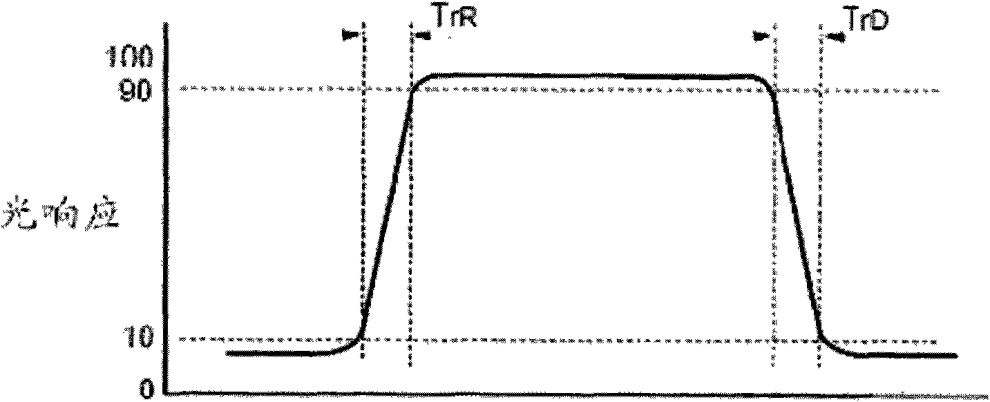
[0029] Figure 4A Middle b is the timing diagram of the liquid crystal display actually completing the response. Due to the response time TrR of the liquid crystal molecules (for the convenience of illustration, this embodiment assumes that the G-G response time of the liquid crystal is 2 ms), the first line of the LCD screen is refreshed with the data of the current image field at the time t1, and the liquid cry...

Embodiment 2

[0032] Figure 5A It is a schematic diagram of the backlight scanning control device of the present invention. As shown in the figure, the liquid crystal display screen 501 and the backlight unit 502 are divided into four corresponding areas A, B, C, and D in the row direction, and the area division is the same as Figure 4B The division method in is consistent. The scanning circuit 503 receives continuous left and right eye image fields with a certain parallax, and the image fields are consistent with Figure 4A The left and right image field signals represented by middle a are consistent. The scanning circuit 503 alternately refreshes the liquid crystal display 501 with the received data of the left and right eye image fields. The scanning circuit 503 generally refreshes the liquid crystal display 501 line by line with the data of the current image field in order from top to bottom. The scanning circuit 503 includes: a row scanning circuit 503A, driving to open one row o...


PUM


Abstract

The invention provides a backlight scanning control method and device of a 3D liquid crystal television, and a corresponding 3D liquid crystal television. By the mode of backlight control, the backlight scanning control method and device can realize the purpose of displaying images of the left eye and the right eye at different time and can eliminate the crosstalk of the images of the left eye andthe right eye on the basis of no increase of the field frequency, thereby achieving good 3D display effect.

Description

technical field [0001] The present invention relates to a 3D liquid crystal television, and more particularly, to a backlight scanning control method and device for a 3D liquid crystal television. Background technique [0002] Stereoscopic TV or 3D TV technology is mainly based on the principle of human vision to obtain two images of the same object at different angles, and project these two images into the left and right eyes of the person respectively, so that the left and right eyes of the person can be seen. The images in the eyes have a certain parallax, and the brain synthesizes the left and right eye images with parallax to produce depth perception, that is, to form a stereoscopic image display effect. [0003] Various methods of generating and displaying stereoscopic images currently exist. In terms of display, it includes the use of color filters or polarizing lenses to separate left and right eye images, and the use of shutter devices to instantaneously select the...

Claims


Application Information

Patent Timeline
Patent Type & Authority Applications(China)
IPC IPC(8): G09G3/36H04N13/04
Inventor 尚军辉高维嵩李春圃苗永平董玉珍
Owner HISENSE VISUAL TECH CO LTD
Why Eureka
Try Eureka