Battery pack

A technology for battery packs and batteries, which is applied to battery pack components, circuits, electrical components, etc., and can solve problems such as increasing the frequency of consumers replacing battery packs, the lack of guarantee for the safety of operators, and the reduction of battery unit life.

Active Publication Date: 2010-02-17
POSITEC POWER TOOLS (SUZHOU) CO LTD
View PDF0 Cites 11 Cited by
  • Summary
  • Abstract
  • Description
  • Claims
  • Application Information

AI Technical Summary

Problems solved by technology

The existing lead-out connectors used on the battery pack are all made of a thin metal sheet. During use, for example, when the hand-held electric tool with the battery pack installed is in operation, especially when the hand-held If the power tool continues to work with a high current for a long time, the temperature on the connecting piece of the terminal will rise sharply, which will cause the temperature of the plastic sh

Method used


Image

  • Battery pack
  • Battery pack
  • Battery pack

Examples


no. 1 approach

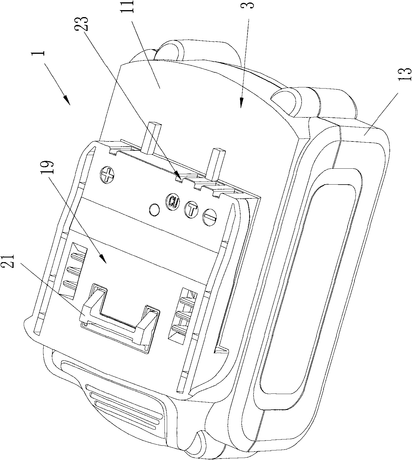
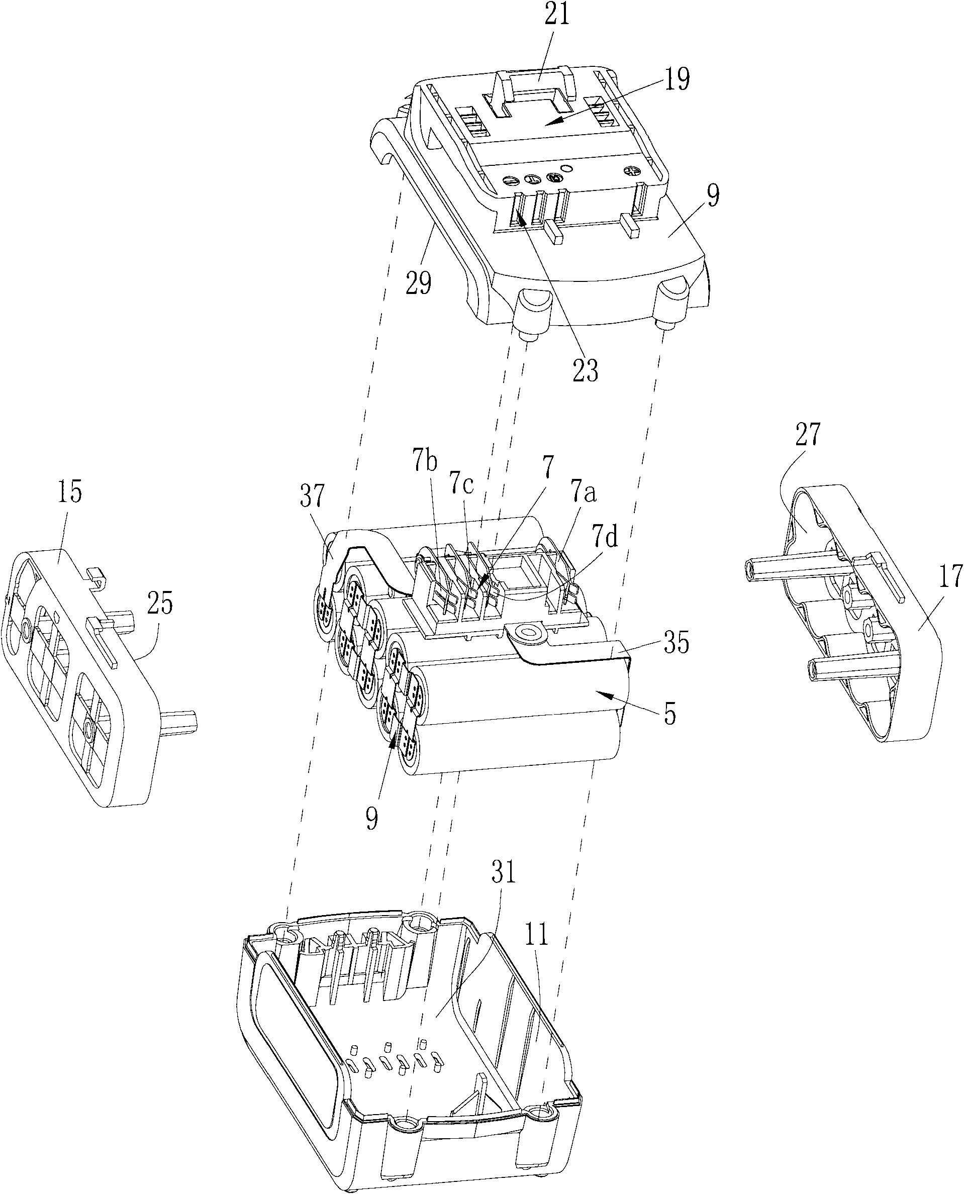
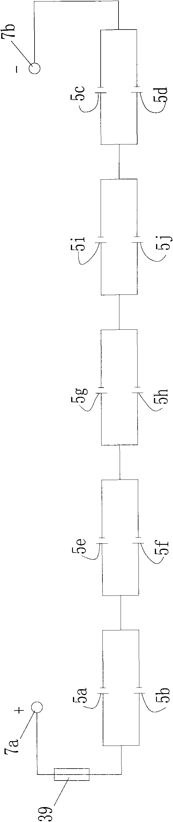
[0056] refer to Figure 1 to Figure 2 A battery pack 1 includes a casing 3, a plurality of battery cells 5 accommodated in the casing 3 and a plurality of connecting terminals 7 exposed outside the casing. Several battery cells 5 are electrically connected through the battery connecting piece 9 .

[0057] The casing 3 includes an upper casing 11 , a lower casing 13 , a first side bracket 15 and a second side bracket 17 . The upper part of the upper housing is provided with a mating area 19, which is used for mating with a mating area (not shown) provided on an electric tool or a charger, and a card is provided on the mating area 19 Buckle 21, the buckle 21 is used to match with the slot (not shown) provided on the electric tool or the charger so as to reliably connect the battery pack 1 thereon. An opening 23 is further provided on the upper part of the upper housing 11 for allowing the connection terminals 7 to pass through.

[0058] further reference image 3 , in the pr...

Embodiment approach

[0078] The present invention can also have other embodiments, for example as follows:

no. 2 approach

[0080] refer to Figure 11 It is the second embodiment of the present invention, and the same parts as the first embodiment will not be repeated here. The main difference between this embodiment and the first embodiment is that each battery group consists of three battery units 61, 62, 63 Formed in parallel, the positive pole or negative pole or the positive and negative pole terminal connection piece includes a first nickel piece 41a, a second nickel piece 43a and a third nickel piece 44a. One end of the first nickel sheet 41a is welded to the positive / negative terminal of the first battery unit 61, the other end is connected to the positive / negative terminal; one end of the second nickel sheet 43a is welded to the positive / negative terminal of the second battery unit 62, and the other end is connected to the positive / negative terminal of the second battery unit 62, One end is connected to the positive / negative terminal; one end of the third nickel sheet 44a is welded to the ...


PUM


Abstract

The invention provides a battery pack, which comprises a shell, an anode terminal, a cathode terminal, a plurality of battery units, a battery connecting sheet, an anode leading-out terminal connecting sheet and a cathode leading-out terminal connecting sheet, wherein the plurality of battery units are accommodated in the shell; the battery connecting sheet is used for electrically connecting theplurality of battery units; the anode leading-out terminal connecting sheet is used for connecting at least one of the plurality of battery units with the anode terminal; the cathode leading-out terminal connecting sheet is used for connecting at least one of the plurality of battery units with the cathode terminal; and at least one of the anode leading-out terminal connecting sheet and the cathode leading-out terminal connecting sheet comprises a plurality of metal sheets.

Description

technical field [0001] The invention relates to a rechargeable battery pack, in particular to a rechargeable battery pack used in hand-held electric tools. Background technique [0002] Currently known hand-held electric tools, such as hand-held drill tools, hand-held saw tools, etc. usually use either an AC motor or a DC motor as a driving motor. For tools using AC motors, a cable is usually connected to the tail of the tool, through which AC power is supplied from the grid. For tools that use DC motors, there is usually a rechargeable battery pack mounted on the tool to provide power. The rechargeable battery pack usually includes several battery units, and these battery units are electrically connected to each other through battery connecting pieces and housed in a plastic casing. Two positive and negative terminals protrude from the plastic housing for electrical connection with the positive and negative terminals on the tool or charger. The two lead-out connectors re...

Claims


Application Information

Patent Timeline
IPC IPC(8): H01M2/10H01M2/02H01M2/20H01M50/10H01M50/247H01M50/503H01M50/522
CPCY02E60/12Y02E60/10
Inventor 汪方勇
Owner POSITEC POWER TOOLS (SUZHOU) CO LTD
Why Eureka
Try Eureka