Battery current collector, its manufacturing method, and nonaqueous secondary battery

A manufacturing method and current collector technology, which are applied in secondary batteries, electrode manufacturing, battery electrodes, etc., can solve problems such as decreased production efficiency, abnormal formation of protrusions, and tearing of the part where the metal foil and burrs are adhered. To achieve the effect of inhibiting adhesion

Inactive Publication Date: 2010-02-17
PANASONIC CORP
View PDF9 Cites 12 Cited by
  • Summary
  • Abstract
  • Description
  • Claims
  • Application Information

AI Technical Summary

Problems solved by technology

In addition, if the adhesion is strong, the part where the metal foil and the burr are adhered may be torn.
In this way, if the metal foil is damaged, its fragments will adhere to the peripheral surface of the roller, and a more serious problem is that protrusions cannot be formed normally on this part.
This leads to a decrease in production efficiency

Method used


Image

  • Battery current collector, its manufacturing method, and nonaqueous secondary battery
  • Battery current collector, its manufacturing method, and nonaqueous secondary battery
  • Battery current collector, its manufacturing method, and nonaqueous secondary battery

Examples


Embodiment approach 1

[0110] Hereinafter, embodiments of the present invention will be described with reference to the drawings.

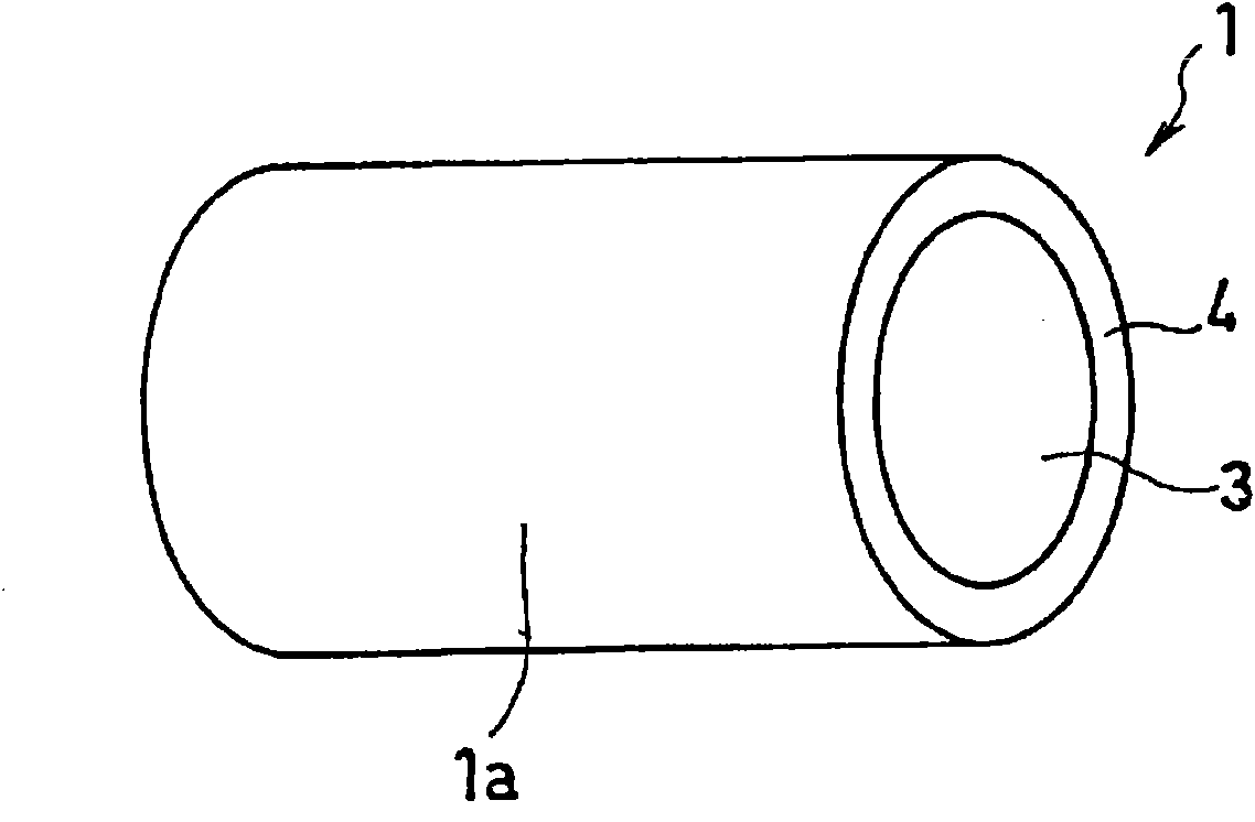
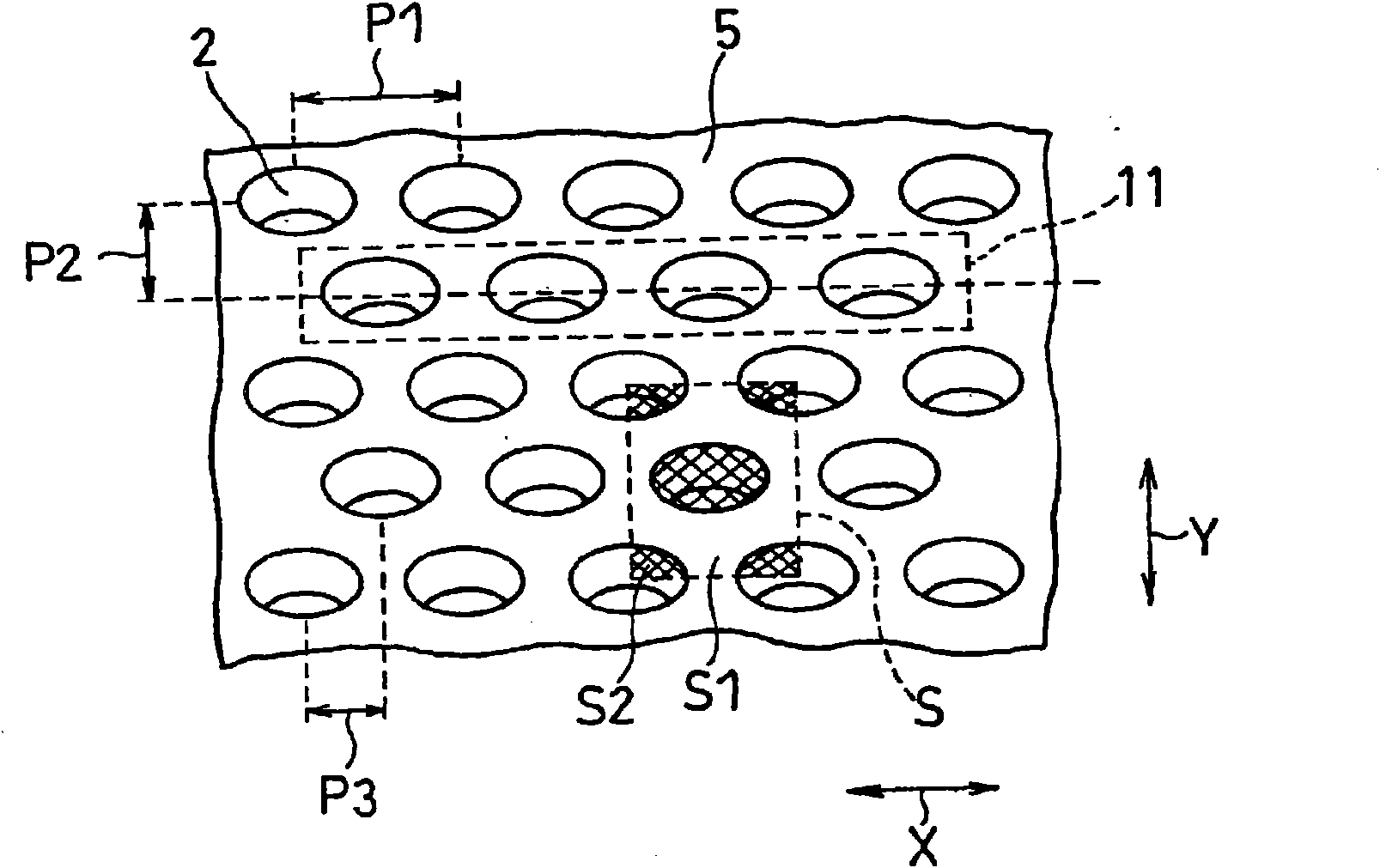
[0111] Figure 1A A schematic configuration of a roller as a processing tool used in the method of manufacturing a battery current collector according to Embodiment 1 of the present invention is shown. Figure 1B It is an enlarged perspective view of a part of its peripheral surface.

[0112] The roller 1 is constituted by forming a plurality of recesses 2 and a pressing flat surface 5 surrounding them on a peripheral surface 1a which is a processing surface. The pressing plane 5 is preferably formed such that the surface roughness (arithmetic mean roughness Ra, hereinafter the same) is 0.8 μm or less. In addition, the concave portion 2 can be formed so as to have a depth of 1 to 15 μm. In addition, the roller 1 is comprised by the core part 3 and the outer peripheral part 4 of mutually different materials as mentioned later in detail. again, in Figure 1A In , the r...

Embodiment 1

[0156] As for the roller, quenched alloy steel of die steel SKD11 was used as the core portion 3 , and an outer peripheral portion in which the peripheral surface 1 a was finished by spraying cemented carbide was used as the outer peripheral portion 4 . Furthermore, by laser processing on the peripheral surface of the roller according to Figure 1B The configuration shown forms a recess 2 . Then, the peripheral surface 1 a of the roller 1 is ground with a plurality of diamond particles having an average particle diameter of 0.5 to 30 μm to remove burrs or bulges formed on the edges of the recesses 2 . This is to prevent the surface roughness of the peripheral surface of the roller from becoming partially rough due to the above-mentioned burrs or bulges. In this way, the pressing flat surface 5, which is the portion other than the concave portion 2, on the peripheral surface of the roller was finished so that the surface roughness (arithmetic mean roughness Ra, the same applie...

Embodiment 2

[0161] The surface roughness of the pressing plane 5 of the above-mentioned upper roll was finished to 0.2 μm. Using this roll, a current collector for a positive electrode having a surface roughness of the base plane 8 of 0.2 μm was produced.


PUM

PropertyMeasurementUnit
surface roughnessaaaaaaaaaa
particle sizeaaaaaaaaaa

Abstract

Provided is a battery current collector made of a metal foil and carrying at least an active substance for an anode or an active substance for a cathode. On at least one face of the metal foil, a compressed base face is formed, and incompressive protrusions are formed, accordingly as the base face is formed, and are arranged at a predetermined spacing. The base face has its surface roughness madedifferent from that of the protrusions and set preferably to an arithmetic average roughness of 0.8 ¢mu!m or less.

Description

technical field [0001] The present invention mainly relates to a current collector for batteries, a method for producing the same, and a non-aqueous secondary battery. More specifically, it relates to a battery current collector suitable for use in a non-aqueous secondary battery represented by a lithium secondary battery, a method for producing the same, and a non-aqueous secondary battery. Background technique [0002] Lithium-ion secondary batteries (hereinafter referred to simply as lithium secondary batteries), which are non-aqueous secondary batteries, have characteristics such as high voltage and high capacity, and are relatively easy to miniaturize and reduce weight. Therefore, they are mainly used as power sources for portable electronic devices recently. utilization has increased significantly. A representative lithium secondary battery uses a carbonaceous material that can intercalate and extract lithium as an active material for the negative electrode, and uses ...

Claims


Application Information

Patent Timeline
Patent Type & Authority Applications(China)
IPC IPC(8): H01M4/70H01M10/36H01M4/64H01M10/052
CPCY02E60/12H01M4/661Y02E60/122H01M4/78H01M4/664H01M10/052H01M4/667Y10T29/49108Y10T29/49115Y02E60/10H01M4/70H01M4/04
Inventor 西村卓宽古结康隆野野下孝平冈树
Owner PANASONIC CORP
Why Eureka
Try Eureka