Feed hopper of novel corn thresher

A thresher and feeding hopper technology, applied in threshing equipment, agricultural machinery and implements, applications, etc., can solve the problems of batch feeding, low threshing efficiency, time-consuming and labor-intensive problems

Inactive Publication Date: 2010-02-24
唐满江
View PDF0 Cites 5 Cited by
  • Summary
  • Abstract
  • Description
  • Claims
  • Application Information

AI Technical Summary

Problems solved by technology

Although this single-tube corn thresher has the advantages of clean threshing, no broken cores, and no need for cleaning, the feed can only be fed one by one manually, which is time-consuming and labor-intensive, and the threshing efficiency is low.
At present, in the market of small corn threshers, the single-tube structure has been copied to produce a new type of double-tube or multi-tube horizontal and vertical corn thresher units, but the method of manual single feeding is still used, and batch feeding has not been solved. The problem

Method used


Image

  • Feed hopper of novel corn thresher
  • Feed hopper of novel corn thresher
  • Feed hopper of novel corn thresher

Examples


Embodiment 1

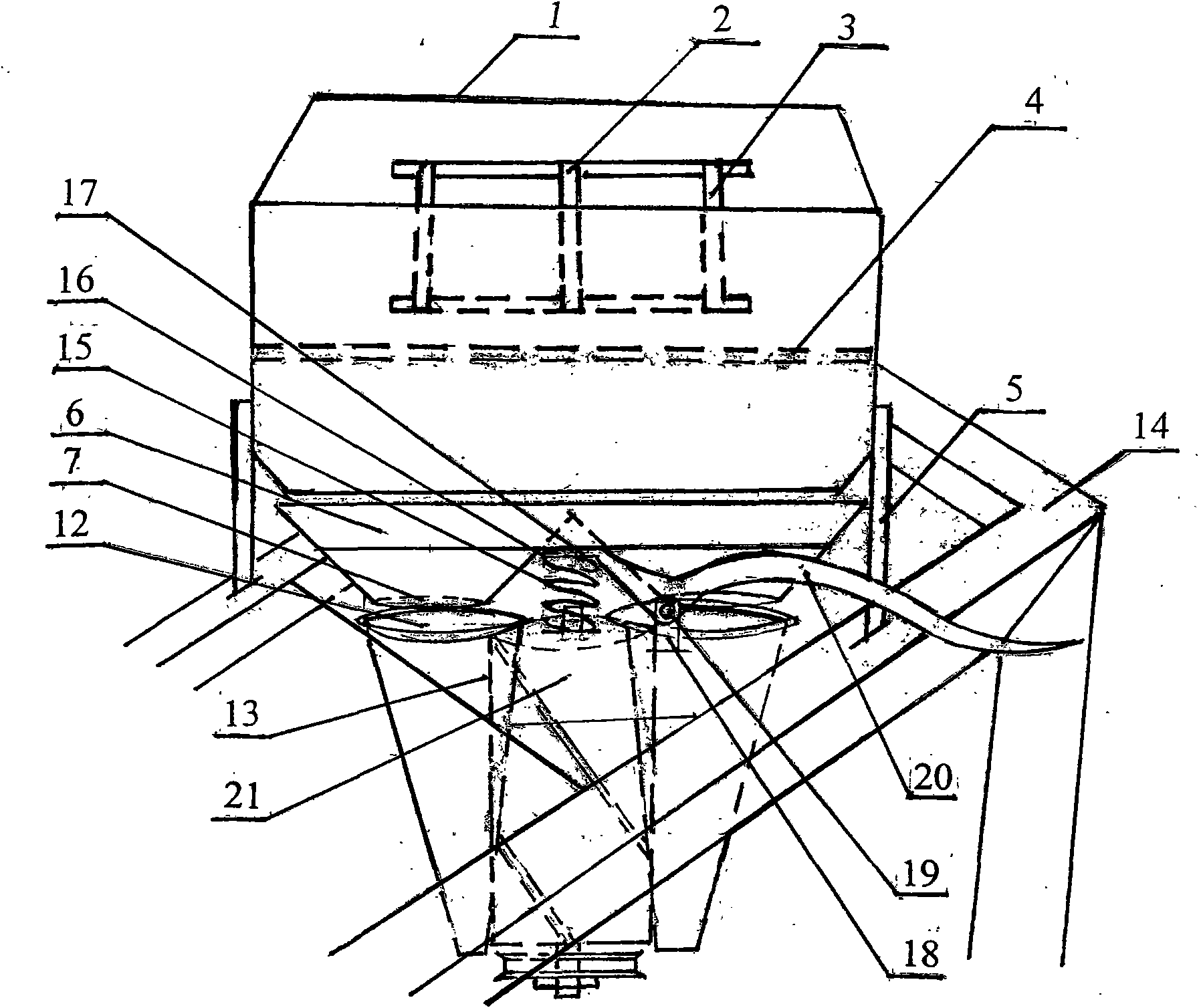
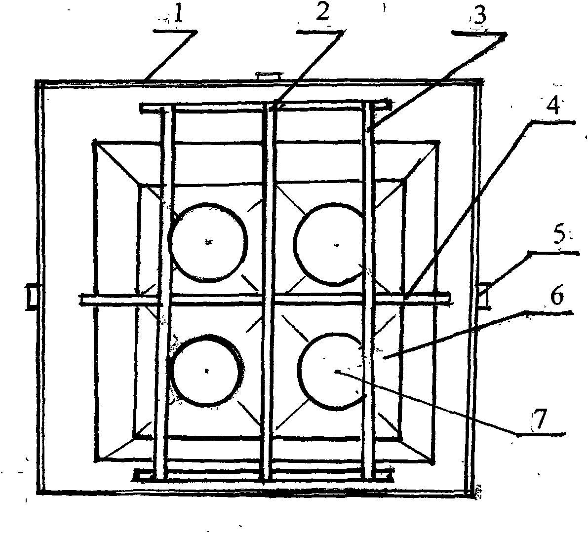
[0014] Feeding hopper of vertical corn thresher

[0015] Barrier screens 2 are arranged on the upper layer in the feed bucket frame 1, and there is a certain distance between each barrier bar 3 of the barrier screens 2. The middle layer in the feed bucket frame 1 is arranged with a crossbar 4, and the crossbar 4 is placed in the middle, and crosses with the upper fence sieve bar 3 in the shape of a "cross" when viewed from above. On the lower floor of the feed hopper frame 1, set up the corn cob outlet, namely the discharge hopper 6. The discharge hopper 6 is the number of the threshing pipes 12 of the corn threshing unit, and separates one or more threshing pipes from the corn threshing unit with a partition plate. 12 corresponding funnel-shaped outlets. There is crank 20 below the discharge hopper 6, and spring 15 is arranged below the front end of crank 20. Spring 15 and crank support block 18 are fixed on the frame plate 21. The handle 20 is movably connected with the cr...

Embodiment 2

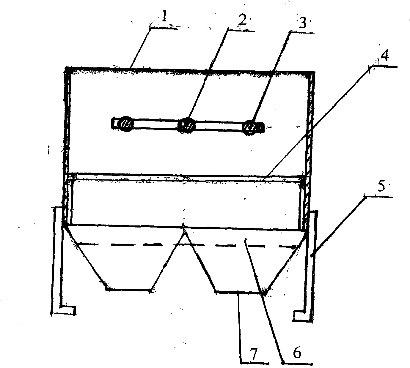
[0017] Feed hopper of horizontal corn thresher

[0018] The feed hopper of the horizontal corn thresher is different from the feed hopper of the vertical corn thresher in that the cross bar 4 in the middle layer of the feed hopper of the vertical corn thresher is replaced with a flat funnel 8, and one side of the flat funnel has an elbow 9. There is a discharge trough 10 set up corresponding to the threshing pipe of the corn thresher under the flat funnel 8 . The bottom floor 11 of the discharge chute 10 has a certain inclination. After the corn cobs are put into the feed hopper frame 1, they fall through the fence screen 2 in the feed hopper frame 1, and then enter the flat funnel 8, the flat funnel elbow 9 blocks the corn cobs falling from the top and cannot fall vertically into the discharge chute 10. Do not allow a large amount of corn cobs to fall directly into the discharge chute 10 to prevent the discharge chute 10 from being blocked, so as to ensure that the corn cobs...


PUM


Abstract

The invention discloses a feed hopper of a novel corn thresher, which is arranged according to the threshing and feeding requirements of a tubular corn thresher and the shape and the size of a corn cob and used for the mass feed of a vertical type corn thresher and a horizontal type corn thresher. The feed hopper is divided into an upper layer, a middle layer and a lower layer, wherein the upper layer is provided with a fence sieve, and the lower layer is provided with a corn cob outlet; the middle layer of the feed hopper suitable for the vertical type corn thresher is provided with a horizontal rod, and the middle layer of the feed hopper suitable for the horizontal type corn thresher is provided with a flat hopper. The corn cobs with different sizes in disorder are fed into the feed hopper in batch during working, and the corn cobs fed in batch can sequentially fall one by one to enter a threshing pipe of the corn thresher to thresh under the actions of mutual impact and manual pullthrough the automatic adjustment of the fence sieve and a horizontal rod or the flat hopper; the problem of power and time waste of single manual feed of a small corn thresher is solved, and the batch feed speed and the threshing efficiency are both high.

Description

technical field [0001] The invention belongs to a threshing machine, in particular to a feed hopper of a corn threshing machine. Background technique [0002] Existing small-sized corn threshers suitable for farmers in Southwest my country consist of a threshing drum and a threshing pipe. Although this single-tube corn thresher has the advantages of clean threshing, no broken cores, and no need for cleaning, the feed can only be fed one by one manually, which is time-consuming and labor-intensive, and the threshing efficiency is low. At present, in the market of small corn threshers, single-tube structure has been copied to produce double-tube or multi-tube horizontal and vertical new corn thresher units. The problem. Contents of the invention [0003] The purpose of the present invention is to provide a feeding hopper that can arrange batches of corn cobs that are put into the hopper into the threshing pipe one by one and continuously enter the threshing pipe without ma...

Claims


Application Information

Patent Timeline
Patent Type & Authority Applications(China)
IPC IPC(8): A01F11/06A01F12/10
Inventor 唐满江
Owner 唐满江
Why Eureka
Try Eureka