Plate-type falling film evaporator

A falling film evaporator, plate-type technology, applied in the field of plate-type falling film evaporator, can solve the problems of uneven film distribution, difficult evaporation effect, corrosion and perforation, etc., to achieve the effect of improving evaporation effect, ensuring safe operation, and ensuring evaporation effect

Active Publication Date: 2010-02-24
ZHANGHUAJI SUZHOU HEAVY EQUIP CO LTD
View PDF0 Cites 4 Cited by
  • Summary
  • Abstract
  • Description
  • Claims
  • Application Information

AI Technical Summary

Problems solved by technology

The plate type falling film evaporator with the above structure has some disadvantages as follows: 1. Some non-condensable gases will be entrained in the heating steam in the heating plate of the heater of the plate type falling film evaporator, and the existence of non-condensable gases seriously affects the evaporation. The heat transfer effect of the device
For example, if there is 1% non-condensable gas in the heating steam, the total heat transfer of the heater will drop by 60%, so the non-condensable gas must be discharged in time. The plate falling film evaporator with the above structure can discharge very little non-condensable gas. Because the density of non-condensable gas is slightly higher than that of water vapor, a considerable amount of non-condensable gas is deposited in the evaporator because it cannot be discharged in time, which seriously affects the heat transfer efficiency of the heater; 2. Due to the evaporation of the solution They are all fed with low boiling point. The upper heater not only undertakes the evaporation of the solution, but also the temperature rise of the solution. The heat required is larger than that of the lower heater. Relatively speaking, the heat required by the lower heater is smaller than that of the upper heater. , so the plate type falling film evaporator with the above structure does not make good use of heat, and cannot guarantee the temperature of the solution on the entire longitudinal section of the evaporator and the heat required for evaporation, and it is difficult to ensure the evaporation effect; 3. The plate type falling film with the above structure The evaporator adopts one-time film distribution, but the one-time film distribution is prone to uneven film distribution, which leads to dry evaporation of the heating plate, severe corrosion and perforation, and the evaporator cannot operate

Method used


Image

  • Plate-type falling film evaporator
  • Plate-type falling film evaporator
  • Plate-type falling film evaporator

Examples


Embodiment Construction

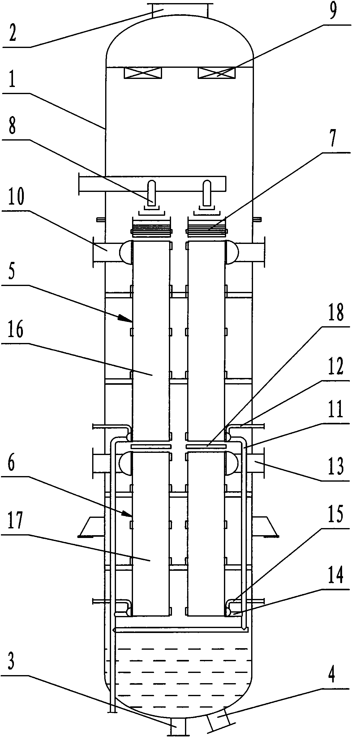
[0012] The structure and working principle of the plate type falling film evaporator of the present invention will be further described in detail below in conjunction with the accompanying drawings.

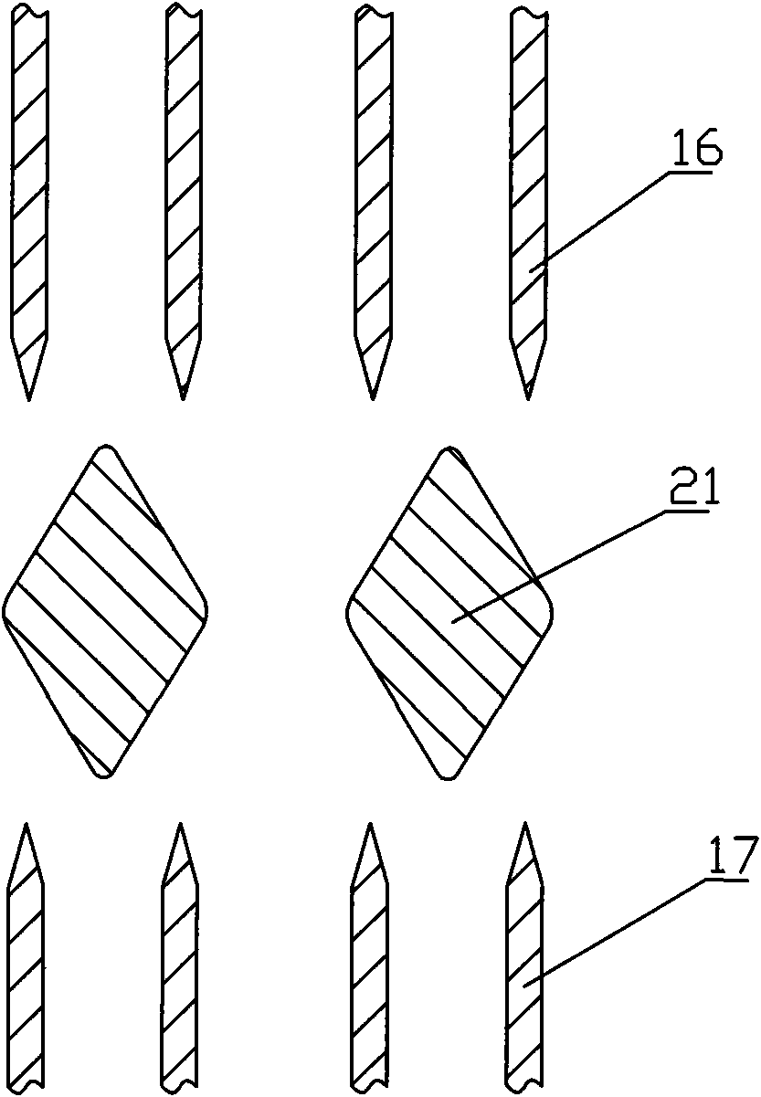
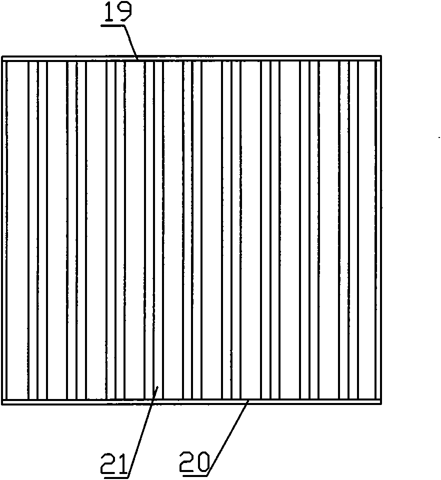
[0013] Such as figure 1 As shown, a plate type falling film evaporator includes: a housing 1, a steam outlet 2 is provided on the top of the housing 1, a solution outlet 3 and a circulating solution outlet 4 are provided on the bottom of the housing 1, and a The upper heater 5 and the lower heater 6 are provided above the upper heater 5 with the upper film distributor 7, the liquid inlet pipe outlet 8 is located above the upper membrane distributor 7, the demister 9 is located below the steam outlet 2, and the upper heating The upper steam inlet 10 of the device 5 is arranged at the upper end of the upper heater 5, and the upper condensed water outlet 11 is arranged at the lower end of the upper heater 5, and an upper non-condensable gas outlet 12 is also communicated with the up...


PUM


Abstract

The invention discloses a plate-type falling film evaporator which can timely discharge all the non-condensable gases, reasonably uses heat quantity and features uniform filming. The plate-type falling film evaporator comprises a shell, a vapor outlet is arranged at top of the shell, a solution outlet and circular solution outlet are arranged at bottom of the shell, the shell is internally provided with an upper heater and a lower heater, an upper layer filming device is arranged above the upper heater, the outlet of a liquid inlet tube is arranged above the upper layer filming device, a demister is arranged below the vapor outlet, the vapor inlets of the heaters are arranged at the upper ends of the heaters, a condensed water outlet is arranged at the lower ends of the heaters, and the condensed water outlet is also communicated with a non-condensable gas outlet; the length ratio of an upper heating plate composing the upper heater and a lower heating plate composing the lower heateris 5.5-6.0:4.5-4.0. The invention is applicable to places of solution evaporation.

Description

technical field [0001] The invention relates to a plate type falling film evaporator. Background technique [0002] The plate type falling film evaporator plays a very important role in the chemical industry. The traditional plate type falling film evaporator includes: a shell with a steam outlet on the top of the shell, and a solution outlet and a circulating solution outlet on the bottom of the shell. An upper heater and a lower heater are provided, and the length of the upper heating plate constituting the upper heater is equal to the length of the lower heating plate constituting the lower heater. The middle parts of the upper and lower heaters are respectively provided with steam inlets. The upper ends of the heaters are respectively provided with non-condensable gas outlets, the lower ends of the upper and lower heaters are respectively provided with condensed water outlets, and the upper film distributor is arranged above the upper heater, and the outlet of the liquid...

Claims


Application Information

Patent Timeline
Patent Type & Authority Applications(China)
IPC IPC(8): B01D1/00B01D1/22
Inventor 杜修权徐萌邹妮康李军花朱仁华
Owner ZHANGHUAJI SUZHOU HEAVY EQUIP CO LTD
Why Eureka
Try Eureka