

Elevating mechanism of lifting bar of computerized flat knitting machine
A lifting mechanism and needle lifter technology, which is applied in knitting, weft knitting, textiles and papermaking, etc., can solve the problems of many moving links of needle lifter lifting, complicated structure, impact of needle lifter, etc., to achieve convenience and Fast cleaning, less movement links, and the effect of ensuring reliability
- Summary
- Abstract
- Description
- Claims
- Application Information
AI Technical Summary
Problems solved by technology
Method used
Image

Examples
Embodiment Construction
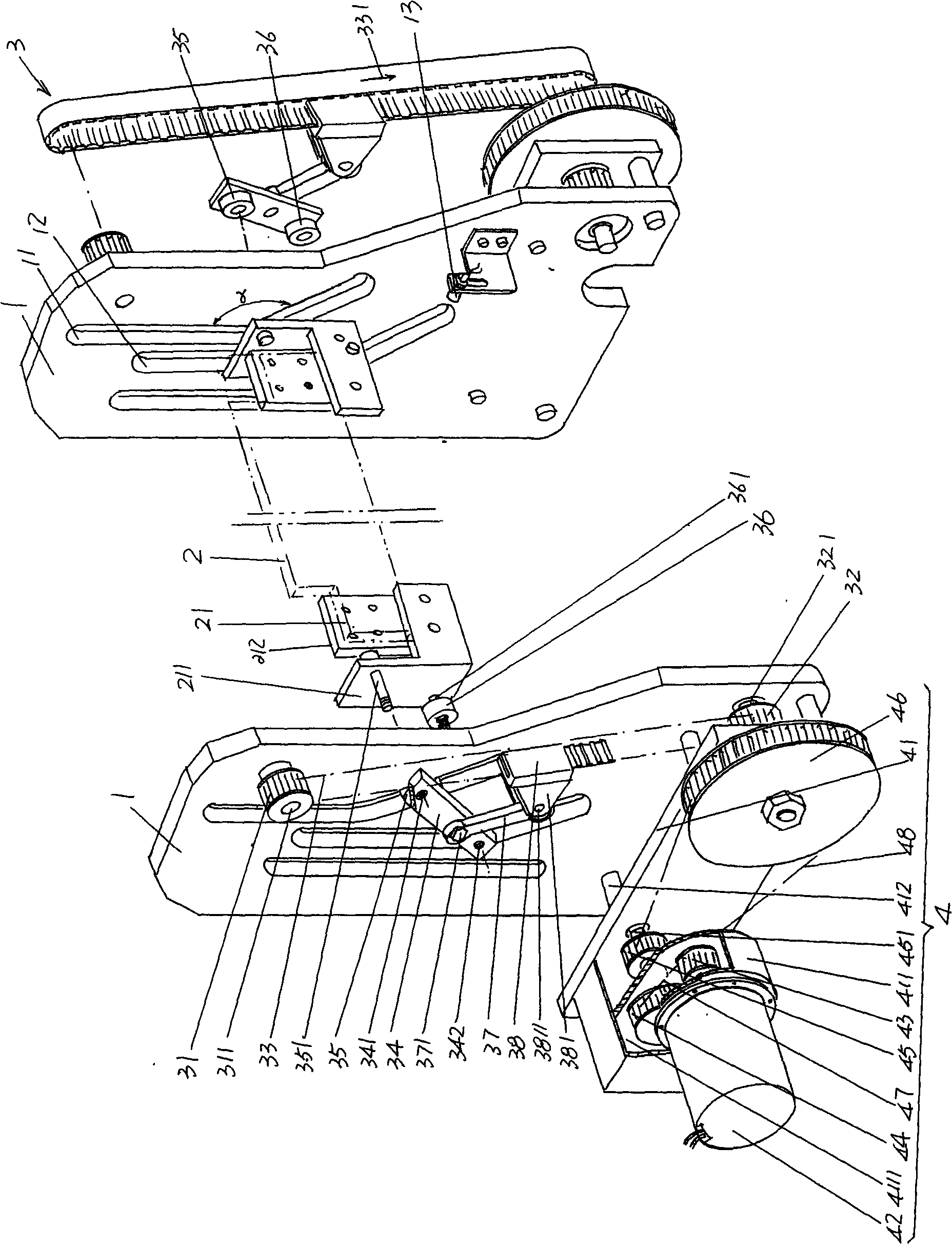
[0020] please see figure 1 , a pair of wallboards 1 is provided, and the pair of wallboards 1 is fixed to the computerized flat knitting machine below the cabinet 6 ( Figure 4 The corresponding two sides of the length direction of shown), the distance between a pair of wallboards 1 is suitable for the length of needle lifting board 2. Since the shape, structure, installation method and working principle of a pair of wallboards 1 are completely the same, the applicant will choose one to describe in detail below. Since the width of the upper end of the wallboard 1 is smaller than that of the lower end, there is a trend of gradually widening from top to bottom, so the shape of the wallboard 1 tends to be pipa-shaped. The upper end of the height direction of the wallboard 1 is provided with first and second moving grooves 11, 12, and the upper ends of the first and second moving grooves 11, 12 are straight grooves, while the lower ends are inclined grooves, and the straight groo...
PUM
 Abstract
Description
Claims
Application Information