Cutting insert and cutting tool equipped therewith

A technology for cutting blades and cutting tools, which is applied in the direction of cutting blades, tool holders, manufacturing tools, etc., can solve the problem that the chip width cannot be effectively reduced, and achieve the effects of reducing chip width, reducing scratches, and preventing friction

Inactive Publication Date: 2020-11-24
KORLOY
View PDF7 Cites 1 Cited by
  • Summary
  • Abstract
  • Description
  • Claims
  • Application Information

AI Technical Summary

Problems solved by technology

[0009] However, the cutting insert 1 has a problem that the chip width cannot be effectively reduced because the chip is deformed when it hits the four shoulder portions 10b and 10d located at the rear of the insert where little force is applied during cutting

Method used


Image

  • Cutting insert and cutting tool equipped therewith
  • Cutting insert and cutting tool equipped therewith
  • Cutting insert and cutting tool equipped therewith

Examples


Embodiment Construction

[0038] Hereinafter, preferred embodiments of the present invention will be described in detail with reference to the accompanying drawings, which will be apparent to those skilled in the art to which the present invention pertains. However, the description presented herein is only a preferred example for the purpose of illustration and is not intended to limit the scope of the present invention, so it should be understood that other equivalents can be made thereto without departing from the scope of the present invention. and modify.

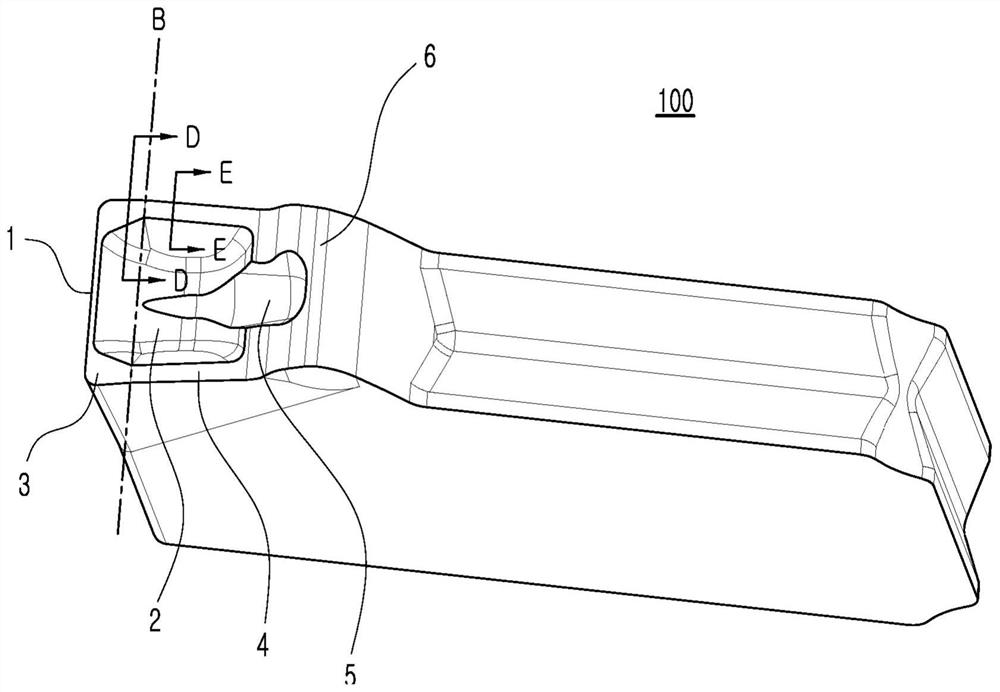
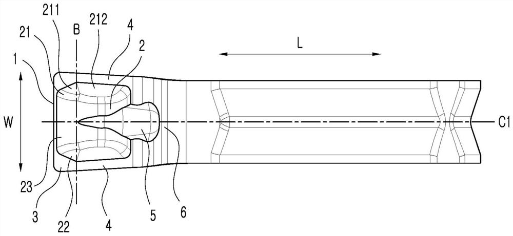
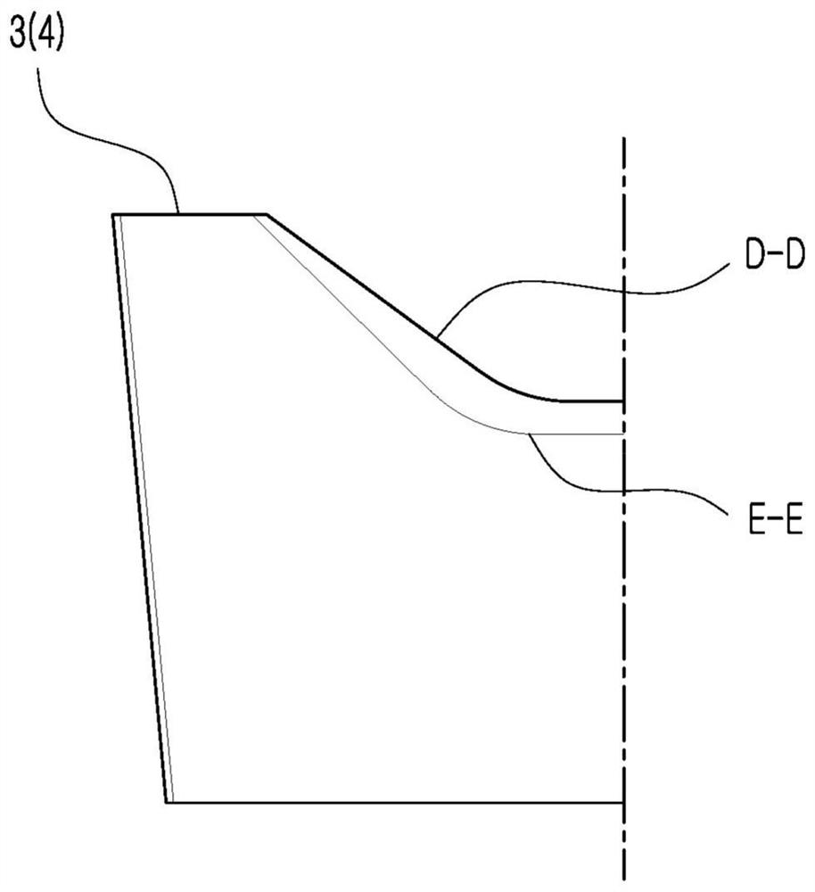
[0039] Such as figure 1 with figure 2 As shown, a cutting insert 100 for grooving according to an embodiment of the present invention includes a front cutting edge 1, a chip breaker 2 extending from the rear of the front cutting edge 1 in the longitudinal direction L of the cutting insert, and a chip breaker formed on the chip breaker. The land portion 3 on both sides of the blade 2, and the inclined surface 4 that is continuous with the lan...


PUM


Abstract

A cutting insert for groove machining is provided, which includes a front cutting edge, a chip breaker groove extending from a rear direction of the front cutting edge in a lengthwise direction of thecutting insert, land portions formed on both sides of the chip breaker groove, and inclined surfaces in continuity with the land portions and extending from the land portions to a rear direction of the cutting insert, wherein a distance in a transverse direction between left and right walls of the chip breaker groove gradually increases from an entrance of the chip breaker groove toward a boundary between the land portions and the inclined surfaces, and then gradually decreases upon passing the boundary, and the cutting insert is symmetrical about a longitudinal center line thereof.

Description

[0001] Cross References to Related Applications [0002] This application claims priority from Korean Patent Application No. 10-2019-0059178 filed with the Korean Intellectual Property Office on May 21, 2019, the disclosure of which is incorporated herein by reference in its entirety. technical field [0003] The present invention relates to a cutting insert for grooving and a cutting tool equipped with the cutting insert. Background technique [0004] Generally, cutting inserts are fastened to cutting tools mounted on machine tools and used to cut workpieces made of iron, non-ferrous metals, non-metallic materials, etc., such as machine parts and the like. [0005] Such a cutting insert includes an upper surface, a lower surface oriented in opposite directions, side surfaces connecting the upper surface and the lower surface to each other, and a cutting edge for cutting a workpiece. [0006] Meanwhile, compared with general turning machining, the space for discharging chip...

Claims


Application Information

Patent Timeline
Patent Type & Authority Applications(China)
IPC IPC(8): B23B27/00B23B27/22
CPCB23B27/00B23B27/22B23B27/005B23B27/045B23B27/14B23B29/043B23B2200/087B23B2200/286B23B2220/12
Inventor 莘圣根闵丙勋金哮山金永钦
Owner KORLOY
Why Eureka
Try Eureka