
Line-breaking stoppage electronic controller of knitting machine

An electronic control device and knitting machine technology, which is applied in the direction of knitting, textiles and paper making, can solve the problems of easily damaged knitting machines, affecting the quality of knitting, and consuming knitting materials, and achieves high parking sensitivity, good knitting effect, and economical knitting material effect

Inactive Publication Date: 2010-02-24
韩百峰
View PDF0 Cites 10 Cited by
  • Summary
  • Abstract
  • Description
  • Claims
  • Application Information

AI Technical Summary

Problems solved by technology

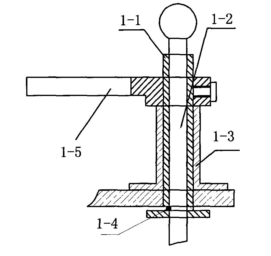
Disadvantages of this kind of mechanical switch device: the broken wire drop needs a heavy load to collide with the claw to stop, so the sensitivity of the broken wire is low, and it is easy to damage the parts of the knitting machine, which affects the knitting quality and consumes knitting materials.

Method used


Image

  • Line-breaking stoppage electronic controller of knitting machine
  • Line-breaking stoppage electronic controller of knitting machine
  • Line-breaking stoppage electronic controller of knitting machine

Examples


Embodiment 1

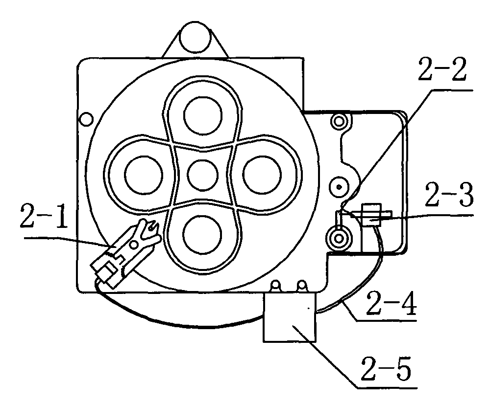
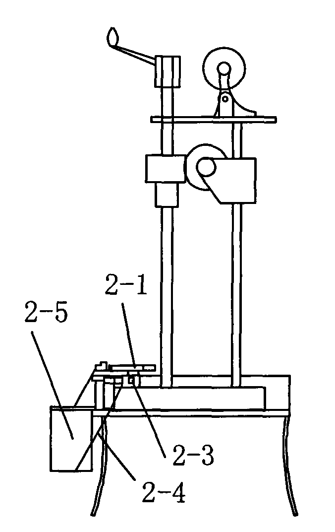
[0022] Embodiment 1: The device includes a sensor device, a controller 2-5 and an electromagnetic switch, and both the sensor device 2-1 and the electromagnetic switch are connected to the controller 2-5 through a wire 2-4.

[0023] The electromagnetic switch includes an electromagnet 2-3 and a switch handle 2-2, the electromagnet 2-3 is located at one end of the switch handle 2-2, and the switch handle 2-2 is located within the stroke of the electromagnet 2-3. The sensor device 2-1 includes a bracket and a switch, and the switch is installed on the bracket; the sensor device is located at one side of the weaving machine runway.

[0024] The support includes a claw 2, a switch 3, a claw shaft 4, and a return spring 6, the claw 2 is connected to the claw shaft 4, and the switch 3 is located at the rear end of the claw 2; the rear end of the claw 2 is connected Return spring 6 is arranged.

[0025] There is a connection hole in the middle of the claw 2, the front end of the cla...

Embodiment 2

[0027] Embodiment 2: The front end of the finger is an oblique protrusion, the rear end has a protrusion, and the two protrusions are arranged diagonally; or the two protrusions at the front end and the rear end are arranged on the same side of the finger. Others are the same as in Example 1.

Embodiment 3

[0028] Embodiment 3: The two protrusions at the front end and the rear end of the finger are arranged on the same side of the finger. Others are the same as in Example 1.


PUM


Abstract

A line-breaking stoppage electronic controller of knitting machine belongs to the electronic controller used on the knitting machine. The electronic controller comprises a sensor device, a controllerand an electromagnetic switch, the sensor device and the electromagnetic switch are respectively connected with a controller through lead. The electromagnetic switch comprises an electromagnet and a switch handle; and the electromagnet is placed at one end of the switch handle which is positioned in the stroke of the electromagnet. The sensor device is proximity switch, microswitch, limit switch or Hall switch; or the sensor device comprises a bracket and a switch which is equipped to the bracket. The sensor device is placed at the side of B-shaped track of the knitting machine. The advantageof the invention consists in that the controller can convert a mechanical signal of the knitting machine to an electric signal which activates the electromagnet for driving the switch handle to move through the controller for driving the switch handle to move so that the clutch of the knitting machine drops off instantaneously and stop. The line-broken spindle line reel can stop immediately without collision of large load to the mechanical switch, and the component breakage of knitting machine is reduced.

Description

technical field [0001] The invention relates to an electronic controller used on a knitting machine, in particular to an electronic control device for stopping when the knitting machine is broken. Background technique [0002] At present, a broken thread parking device used in weaving is a mechanical type, and the broken thread sensor includes a brake shaft, a switch sleeve, a switch seat, a switch spring and a finger, and a switch sleeve, a switch seat, a switch spring and a finger They are all connected to the brake handle shaft, the switch base is installed on the lower plate, the switch sleeve is sleeved on the brake handle shaft, the switch base is sleeved outside the switch sleeve, the claw is sleeved on the switch sleeve, located at the upper end of the switch base, the switch spring It is connected in the slot at the lower end of the brake handle shaft and the switch sleeve, and is located under the lower plate, and the claw is in the shape of a "herringbone". [00...

Claims


Application Information

Patent Timeline
IPC IPC(8): D04C3/38
Inventor 韩百峰刘建峰
Owner 韩百峰
Learn More