PWM control method for three-level LLC converter

A control method and three-level technology, which can be applied to conversion equipment with intermediate conversion to AC, regulating electrical variables, and control/regulating systems, etc., can solve the design difficulties of three-level LLC converters, large reverse recovery current, Problems such as poor reverse recovery characteristics of parasitic diodes, to achieve the effect of solving the reverse recovery problem

Active Publication Date: 2012-07-04
EMERSON NETWORK POWER CO LTD
View PDF3 Cites 0 Cited by
  • Summary
  • Abstract
  • Description
  • Claims
  • Application Information

AI Technical Summary

Problems solved by technology

[0009] Because the reverse recovery characteristics of the parasitic diode in the MOS tube are generally poor, the reverse recovery current flowing through the bridge arm is very large, and there is a large current change rate di / dt in the bridge arm, which is induced by the gate of the MOS tube. Spike voltage can cause MOS tube to be broken down
It can be seen that the three-level LLC converter controlled by PWM is not equal to the LLC converter controlled by PFM, nor is it different from the ordinary PWM converter. Design presents great difficulty

Method used


Image

  • PWM control method for three-level LLC converter
  • PWM control method for three-level LLC converter
  • PWM control method for three-level LLC converter

Examples


Embodiment Construction

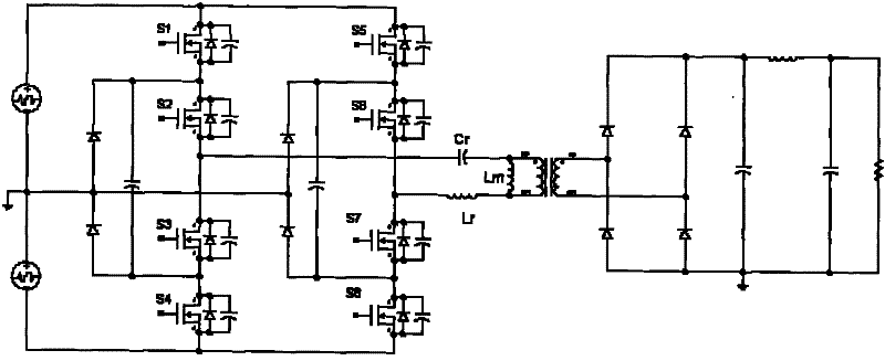
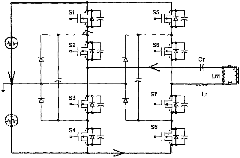
[0025] Please refer to figure 1 and Figure 7 , the PWM control method of the three-level full-bridge LLC converter of an embodiment comprises the following steps:

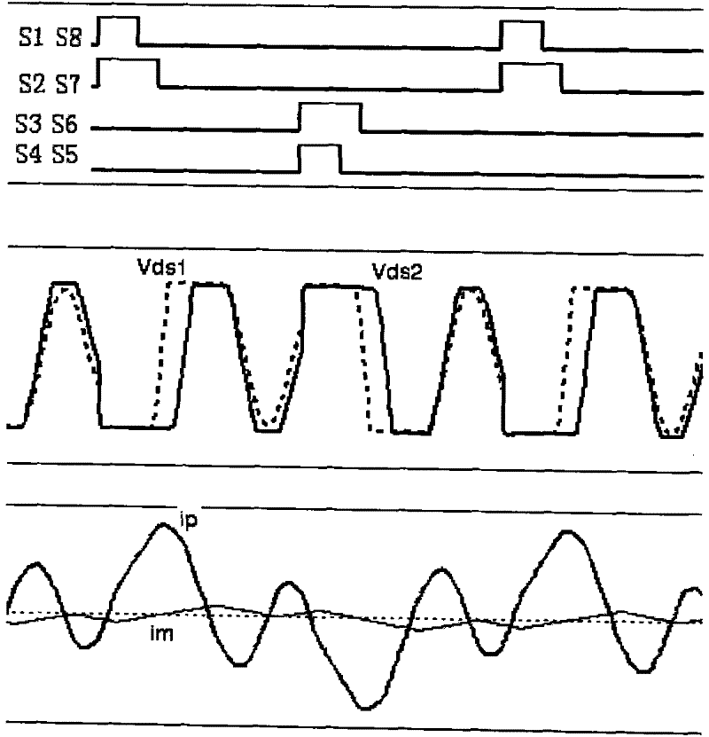
[0026] Step A1: For the four switching tubes S1-S4 on the first bridge arm, determine the minimum duty cycle of the inner tubes S2 and S3 in PWM mode so that the delay of the inner tubes S2 and S3 after the outer tubes S1 and S4 are turned off The length of the off time can avoid the reverse resonance of the resonant current;

[0027] Step A2: Through PWM control, adjust the duty cycle of the outer tubes S1 and S4 respectively according to the gain requirement, and keep the duty cycle of the inner tubes S2 and S3 not lower than the minimum duty cycle accordingly.

[0028] Similarly, for the second bridge arm, the above method is used to control the duty cycle of the inner tubes S6, S7 and the outer tubes S5, S8.

[0029] Since the effective duty cycle of the three-level LLC resonant converter is determined by t...


PUM


Abstract

The invention discloses a PWM control method for a three-level LLC resonant converter. The LLC resonant converter at least comprises a first bridge arm which is connected with a plurality of switch tubes in series and coupled at the primary side of a transformer; the switch tubes comprise two outer tubes close to both ends of the first bridge arm and two inner tubes between the outer tubes; in the PWM mode, the duty ratio of the inner tube is maintained to be no less than the minimum duty ratio when the width modulation of duty ratio is carried out on the inner tube and the outer tube according to the gain demand; the minimum duty ratio is determined according to the requirement that the duration of delaying the turn-off of the inner tube can avoid the reverse resonance of resonance current after the outer tube is turned off. By maintaining the duty ratio of the inner tube to be no less than the minimum duty ratio, the resonance process of current of the primary side of the converter is changed, thereby avoiding generating the problem of the backward recovery of a body diode.

Description

technical field [0001] The invention relates to an LLC resonant converter, in particular to a PWM control method for a three-level LLC converter. Background technique [0002] The LLC resonant converter has been more and more widely used in the industry because of its simple structure and superior soft switching characteristics. In the case of high power and high power density, the three-level LLC resonant converter has gradually become the mainstream topology in the industry due to its advantages of low device stress, low switching loss, and high switching frequency. [0003] LLC resonant converter generally adjusts the gain of the converter by changing the operating frequency, so as to realize the stability and adjustment of the output voltage. In practical applications, considering the loss of power devices and the efficiency of the converter, the operating frequency of the converter cannot be increased without limit, and the frequency modulation range is limited to a ce...

Claims


Application Information

Patent Timeline
Patent Type & Authority Patents(China)
IPC IPC(8): H02M3/28H02M3/335
Inventor 赵敬辉许峰张荣华朱玓瓅
Owner EMERSON NETWORK POWER CO LTD
Why Eureka
Try Eureka