Lighting apparatus using LED
A technology for lighting fixtures and illuminance, applied to lighting devices, fixed lighting devices, lighting and heating equipment, etc., to achieve the effects of eliminating dazzle, reducing dazzle, and reducing emissions
- Summary
- Abstract
- Description
- Claims
- Application Information
AI Technical Summary
Problems solved by technology
Method used
Image
Examples
Embodiment 1
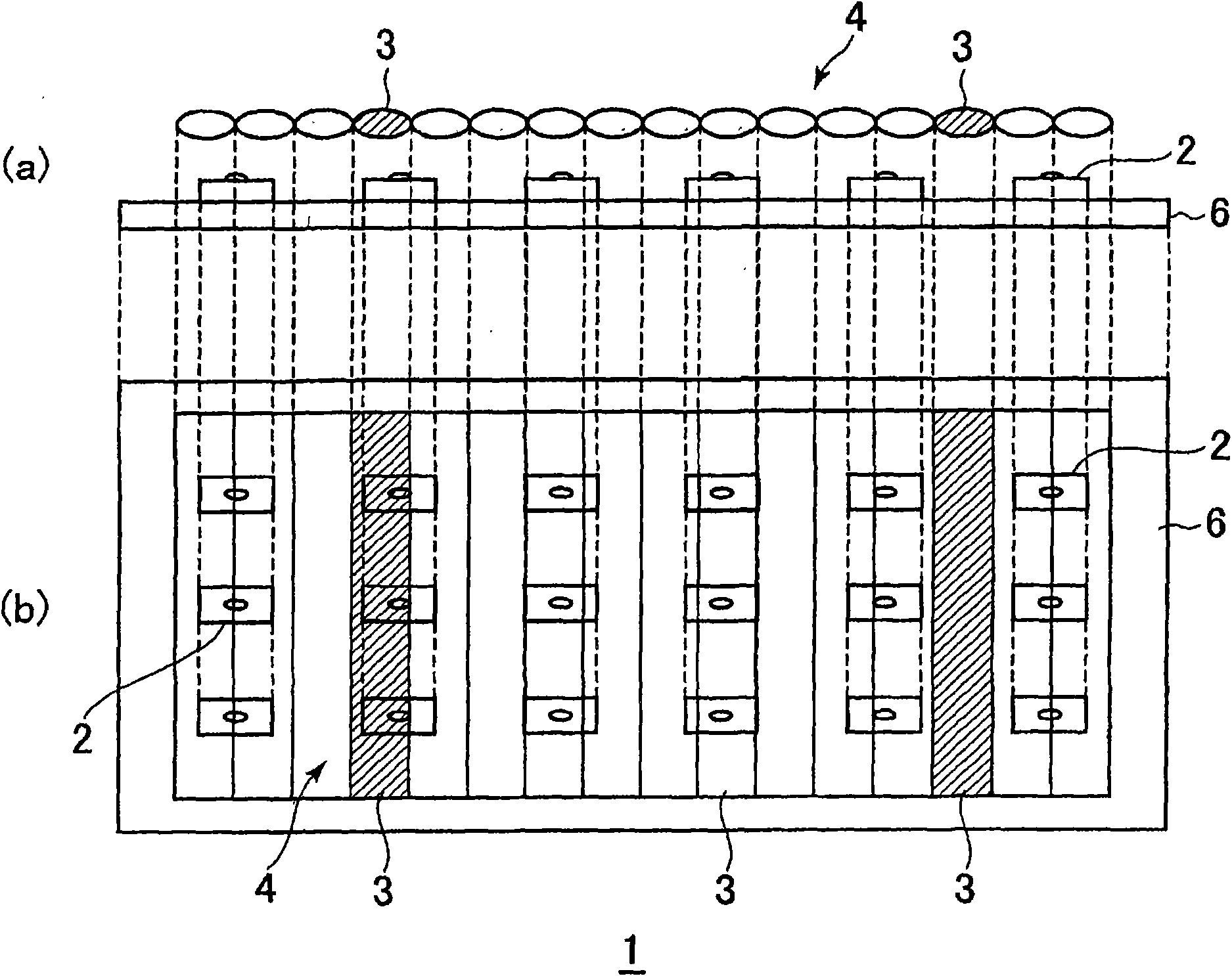
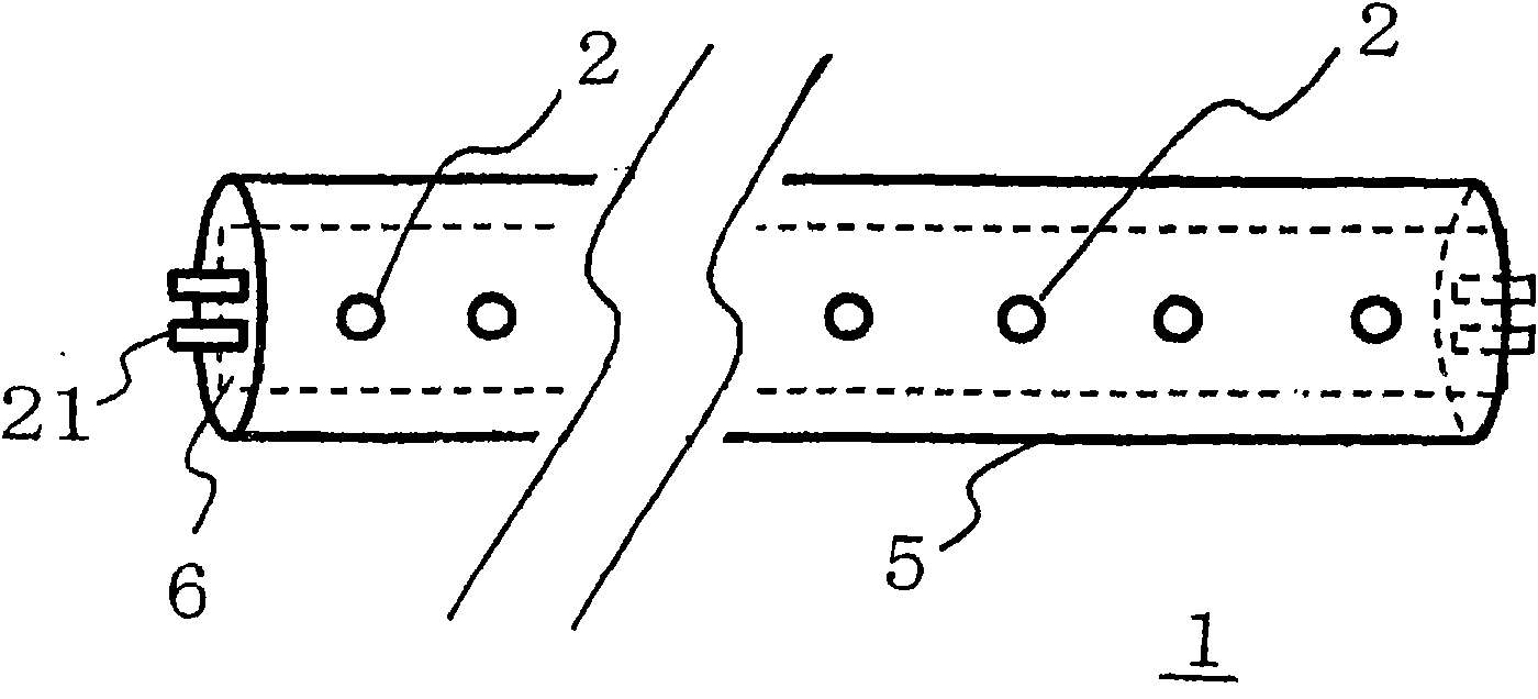
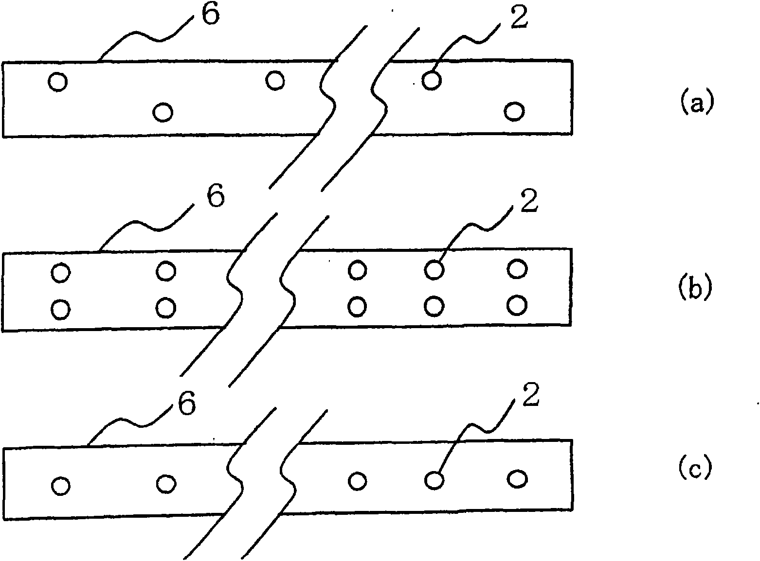
[0104] made Figure 4 with Figure 5 The lighting fixture 1 shown in , which has the same size and appearance as a general-purpose fluorescent lamp 40 type (length 1198mm). That is, if Figure 4 with Figure 5 As shown, there are 3 rows of LEDs 2 , and 96 LEDs in each row use a total of 288 LEDs 2 . Additionally, if figure 2 As shown, the left end and the right end are provided with pins 21 that can be mounted on general-purpose lighting fixtures for fluorescent lamps, and electrical wiring is performed so as to be compatible with general-purpose lighting fixtures for fluorescent lamps.
[0105]As the LED 2, a white LED manufactured by CREE was used. The first light refractor 3 and the inner tube 5 are manufactured integrally. The thickness d1 of the first light refractor 3 is 4 mm, the width L1 is 5 mm, and the thickness of the inner tube 5 is 1 mm. The angle α is 13°. The number of the first light refracting body 3 is as follows Figure 4 with Figure 5 Shown are ...
Embodiment 2
[0109] made Figure 7-9 The lighting fixture 1 shown in , which has the same size and appearance as a general-purpose fluorescent lamp 40 type (length 1198mm). That is, if Figure 7-9 As shown, the second light refracting body 13 is provided on the outside of the slightly thinner lighting fixture that is substantially the same as that of Example 1, and pins 21 are also provided, and electrical wiring is performed to adapt to the lighting fixture for general-purpose fluorescent lamps. Thus, a lighting fixture is manufactured.
[0110] The second light refractor 13 and the outer tube 15 are manufactured in one body. The thickness d2 of the second light refractor 13 is 2.5 mm, and the width L2 is 2.5 mm. The material of the second light refractor 13 is acrylic resin.
[0111] In this way, a lighting fixture adapted to the general-purpose LED fast start method (FLR) is obtained. Hereinafter, the lighting fixture of this invention which has the said 1st light refraction body 3...
Embodiment 3
[0116] Using the lighting fixture A of the present invention, the illuminance of a place away from the lighting fixture A and the illuminance of a place deviated from the illumination angle directly below the lighting fixture A were compared with commercially available fluorescent lamps and lighting fixture Q.
[0117] Measured Figure 11 The illuminance on the plane P existing at a distance of 1 m from the center M of the tubular lighting fixture 1 obtained in Example 1 in the irradiation direction of light. The illuminance at each of the following points was measured: the point where the angle formed by the straight line L passing through M and extending at right angles from the lighting fixture 1 and the plane P is 45° ( Figure 11 BL and BR); 30° location ( Figure 11 AL and AR); and at the point directly below M, that is, at the point where a line passing through M makes an angle of 90° to that plane P (the foot of the perpendicular from M vertically below the plane P) (...
PUM
 Abstract
Description
Claims
Application Information
 - R&D
- Intellectual Property
- Life Sciences
- Materials
- Tech Scout
- Unparalleled Data Quality
- Higher Quality Content
- 60% Fewer Hallucinations
Browse by: Latest US Patents, China's latest patents, Technical Efficacy Thesaurus, Application Domain, Technology Topic, Popular Technical Reports.
© 2025 PatSnap. All rights reserved.Legal|Privacy policy|Modern Slavery Act Transparency Statement|Sitemap|About US| Contact US: help@patsnap.com


