Rotor, its manufacturing method, and electric vehicle

A manufacturing method and rotor technology, applied in the manufacture of motor generators, electric vehicles, electric components, etc., can solve problems such as lack of records

Active Publication Date: 2010-02-24
TOYOTA JIDOSHA KK
View PDF1 Cites 19 Cited by
  • Summary
  • Abstract
  • Description
  • Claims
  • Application Information

AI Technical Summary

Problems solved by technology

Patent Document 1 does not describe a st

Method used


Image

  • Rotor, its manufacturing method, and electric vehicle
  • Rotor, its manufacturing method, and electric vehicle
  • Rotor, its manufacturing method, and electric vehicle

Examples


Embodiment Construction

[0029] Embodiments of the present invention will be described below. The same reference signs are attached to the same or corresponding parts in some cases, and the description thereof will not be repeated.

[0030] In the embodiments described below, when referring to the number of objects, the amount, and the like, the scope of the present invention is not necessarily limited to the number of objects, the amount, and the like unless otherwise described. In addition, in the following embodiments, each constituent element (element) is not an essential element of the present invention unless otherwise specified. In addition, when there are a plurality of embodiments below, it is originally planned that the configurations of the respective embodiments can be appropriately combined unless otherwise specified.

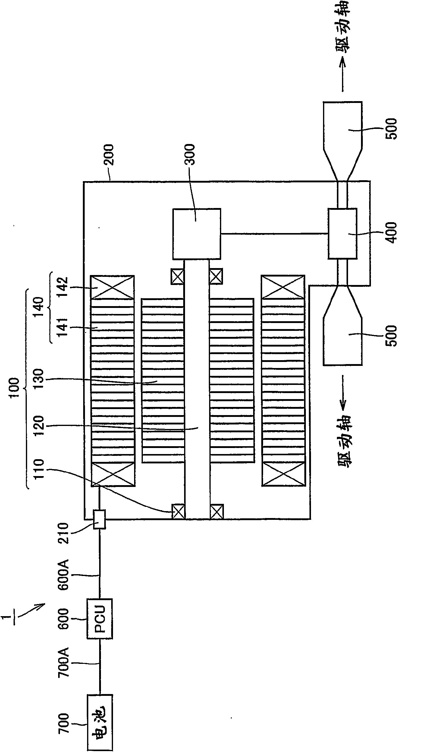
[0031] figure 1 It is a figure schematically showing the structure of the drive unit using the rotor which concerns on one Embodiment of this invention. exist figure 1...


PUM


Abstract

A rotor includes: a rotor core (131) formed by layering a first plate-shaped member (131A) and a second plate-shaped member (131B) and having a first magnet insert hole (1311) and a second magnet insert hole (1312) arranged at an outer position than the first magnet insert hole (1311) in the radial direction; a magnet (132) inserted in the first and the second magnet insert holes (1311, 1312); anda resin portion (133) filling the first and the second magnet insert holes (1311, 1312). The first plate-shaped member (131A) has a first hole portion (1311A) and a second hole portion (1312A) whichrespectively constitute the first and the second magnet insert hole (1311, 1312). The second plate-shaped member (131B) has a portion positioned at least at one end of the rotor core (131) in the axial direction and covering a part of the first hole portion (1311A).

Description

technical field [0001] The present invention relates to a rotor, a method for manufacturing the same, and an electric vehicle, and more particularly, to a rotor included in a rotary electric machine, a method for manufacturing the same, and an electric vehicle including the rotor. Background technique [0002] Japanese Unexamined Patent Publication No. 2005-184968 (Patent Document 1) describes a rotor having a rotor core made of a plurality of electromagnetic steel sheets. Here, the plurality of electrical steel sheets include at least one first steel sheet arranged at the endmost portion and second steel sheets arranged other than that. In addition, each of the plurality of electromagnetic steel sheets has a magnet hole provided to form a magnet attachment hole. Also, the magnet hole of the first steel plate is formed smaller than the magnet hole of the second steel plate. [0003] When embedding the magnets in the rotor core, the magnets are inserted into the magnet inse...

Claims


Application Information

Patent Timeline
IPC IPC(8): H02K1/27H02K15/02
CPCH02K15/03Y02T10/641H02K1/2766B60L2220/14B60L2220/50B60L50/51Y10T29/49012Y02T10/64Y02T10/70
Inventor 水谷龙彦竹内健登
Owner TOYOTA JIDOSHA KK
Why Eureka
Try Eureka