Rotary pulling type water tap

A faucet and pull-up technology, which is applied in the direction of lifting valves, valve details, engine components, etc., can solve problems such as inconvenient operation, easy slipping of rotating threads, and grinding of the cylindrical side of the valve core, etc., to achieve a stable lifting process , prolong the service life, and adapt to a wide range of effects

Inactive Publication Date: 2010-03-03
GUANGDONG BILI DRINKING WATER EQUIPMENT CO LTD
View PDF7 Cites 13 Cited by
  • Summary
  • Abstract
  • Description
  • Claims
  • Application Information

AI Technical Summary

Problems solved by technology

Disadvantages of using this kind of rotary faucet: the cylindrical side of the valve core needs to be ground, and the processing cost is high; because the rotating thread of the valve is easy to slip, the faucet cannot be closed, making it easy to leak
The disadvantages of using this kind of faucet are: the operation is inconvenient; the valve core will also swing left and right when it moves up and down, which will easily cause water to overflow from the side of the door valve.
The third type is the disc-type ceramic core faucet. This kind of faucet is easy to operate, but the water outlet hole is small, which does not meet the requirements of low water pressure and large flow.

Method used


Image

  • Rotary pulling type water tap
  • Rotary pulling type water tap
  • Rotary pulling type water tap

Examples


specific Embodiment 1

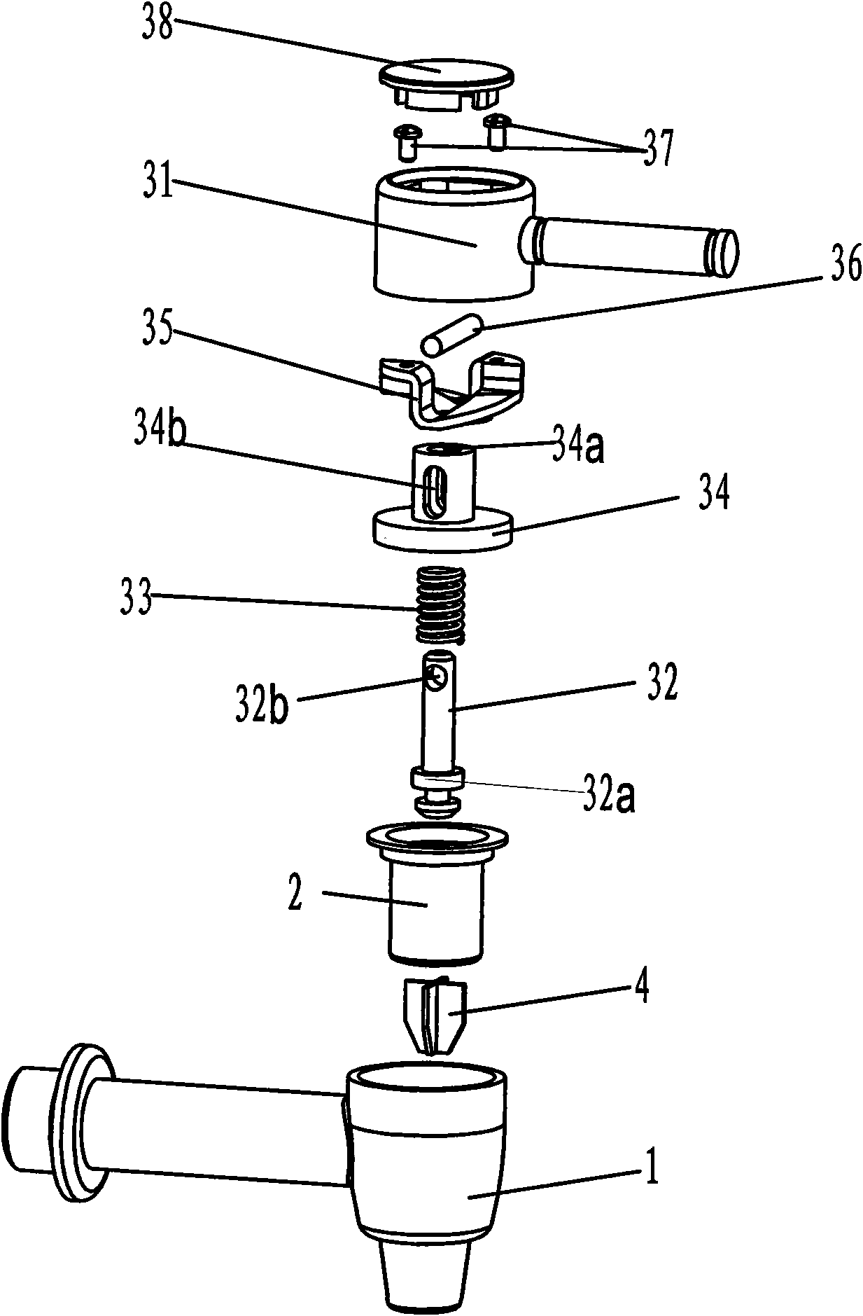
[0031] figure 1 , figure 2 , Figure 3a , 3b , Figure 3c , Figure 3d , Figure 3e , Figure 4 and Figure 5 Constitute the specific embodiment 1 of the present utility model.

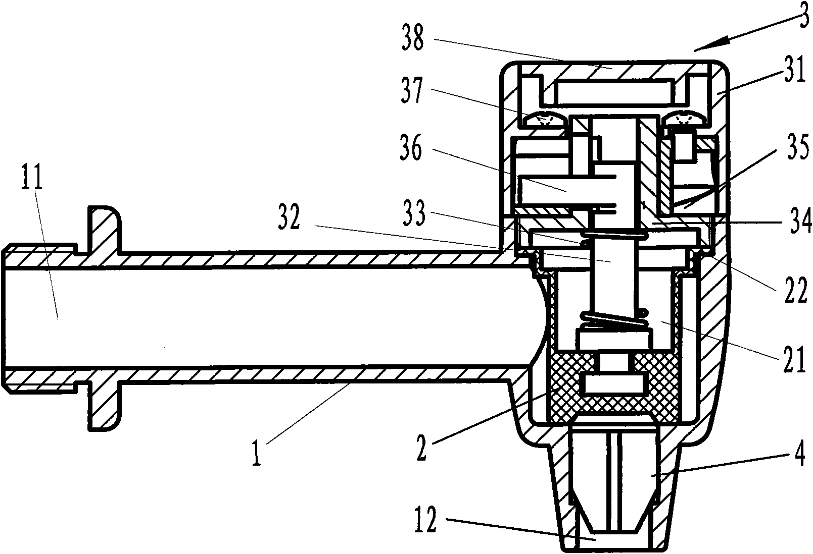
[0032] see figure 1 and figure 2 , this embodiment includes a valve body 1, the valve body is provided with a water inlet 11 and a water outlet 12; a valve core 2 is arranged above the water outlet in the inner cavity of the valve body 1; a rotating lifting mechanism 3 is provided on the valve body 1, so The rotating lifting mechanism 3 is fixedly connected with the valve core 2, and the rotating lifting mechanism 3 drives the valve core 2 to rise or fall in the axial direction, so that the water inlet 11 and the water outlet 12 are connected or cut off. The cross section of the valve body 1 is "right-angled" shape, the left end of its transverse end is provided with a water inlet 11, and the bottom of its vertical end is provided with a water outlet 12; the valve core 2 is arranged in the...

specific Embodiment 2

[0039] The characteristics of this embodiment are: the cross section of the valve body 1 is "T" shape, the left end of the horizontal end of the valve body 1 is provided with a water inlet 11, and the bottom of the vertical end of the valve body 1 is provided with a water outlet 12; 2 is arranged in the inner cavity of the vertical end of the valve body and is located above the water outlet 12. A deflector is provided at the water outlet of the valve body. The spool (2) is made of a silicone spool or a ceramic spool, and is a silicone spool or a ceramic spool. All the other are with specific embodiment 1.


PUM


Abstract

The invention relates to a rotary pulling type water tap which comprises a valve body (1) and a valve core (2), wherein the valve body (1) is provided with a water inlet (11) and a water outlet (12), and the valve core (2) is positioned at a joint of the water inlet (11) and the water outlet (12) in an internal cavity of the valve body (1). The rotary pulling type water tap is characterized in that a cam type rotary lifting mechanism (3) is connected to the valve core (2), the cam output end of the cam type rotary lifting mechanism (3) is fixedly connected with the valve core (2), the rotary input end of the cam type rotary lifting mechanism (3) is exposed out of the valve body (1), a sealing structure is arranged at the joint of the valve body (1) and the cam type rotary lifting mechanism (3), and a connection structure from a rotary motion to a linear motion is formed between the cam type rotary lifting mechanism (3) and the valve core (2). The invention reduces friction between the valve core and the valve body, prolongs the service life of a product greatly, also can bring large flow rate under a condition that the tap is at small water pressure simultaneously, and has wide adaptation range. The invention has the effects of stable pulling process, no water leakage and convenient operation.

Description

technical field [0001] The invention relates to a water faucet, in particular to a rotary lifting type water faucet. It belongs to the technical field of plumbing equipment. Background technique [0002] At present, faucets on the market mainly use the following three methods. The first is a cylindrical rotary valve faucet. The valve core of the faucet is made into a cylinder. The faucet valve drives the cylindrical valve core to rotate, so that the perforation on the side of the valve core communicates with the water hole of the valve body, so that the water flows out, and on the contrary, the faucet is closed. Disadvantages of using this type of rotary faucet: the cylindrical side of the valve core needs to be ground, and the processing cost is high; because the rotating thread of the valve is easy to slip, the faucet cannot be closed, making it prone to water leakage. The second type is the push-pull type faucet. A lever handle is arranged at the valve of the faucet. By...

Claims


Application Information

Patent Timeline
Patent Type & Authority Applications(China)
IPC IPC(8): F16K1/00F16K1/48F16K31/60F16K27/02F16K1/36
Inventor 巫宗权梁裕镳
Owner GUANGDONG BILI DRINKING WATER EQUIPMENT CO LTD
Why Eureka
Try Eureka