
Air duct of uv lamp

A technology of air ducts and light boxes, which is applied in the cooling/heating devices of lighting devices, lighting devices, lighting and heating equipment, etc. It can solve the problems of large deformation of lamp tubes, short life, and uneven cooling of lamp tubes. To achieve the effect of increased service life, small deformation and uniform cooling

Active Publication Date: 2011-12-21
SUZHOU HYCAN HLDG CO LTD
View PDF0 Cites 0 Cited by
  • Summary
  • Abstract
  • Description
  • Claims
  • Application Information

AI Technical Summary

Problems solved by technology

In the prior art, the heat dissipation and exhaust device of this kind of UV lamp does not have a special air duct, but uses a fan to directly exhaust air, which cannot control the uniform air volume, and the lamp tube cannot be cooled evenly, and the deformation of the lamp tube Large, short life; and when UV printing ink is polymerized and hardened, ozone and other waste gas will be generated, and the waste gas will gather around the lamp tube, and some parts of the printing surface will not be illuminated by effective light due to the waste gas barrier, and the surface adhesion of some parts will be weak. Up to the standard, resulting in unstable product quality

Method used


Image

  • Air duct of uv lamp
  • Air duct of uv lamp
  • Air duct of uv lamp

Examples


Embodiment Construction

[0013] The specific structure of the present invention will be further described below in conjunction with the accompanying drawings.

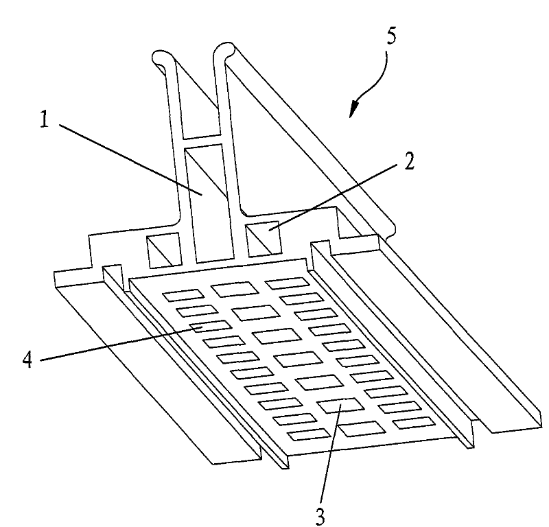
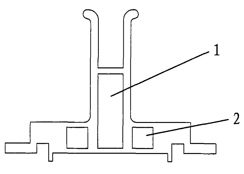
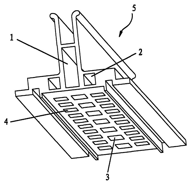
[0014] See attached figure 1 , attached figure 2 Shown, a kind of air channel of UV lamp, on this air channel 5 there is a first cavity 1 for sending fresh air into the lamp box, and the two sides of the first cavity 1 are also provided with respectively for discharging ozone The second chamber 2 of the exhaust gas, the first chamber 1 and the second chamber 2 extend to the entire air duct 5, and the bottoms of the first chamber 1 and the second chamber 2 are respectively provided with a row of holes connected to the air duct. The first hole 3 and the second hole 4 of the channel, and the diameter of the second hole 4 at the bottom of the second cavity 2 is smaller than the first hole 3 at the bottom of the first cavity 1 . The shape of the hole 3 in this embodiment is a square hole. In fact, the first hole 3 and the second hole 4 can also...


PUM


Abstract

The invention relates to an air duct of a UV lamp; the air duct is provided with a first cavity for supplying air in a lamp box and at least a second cavity which is used for exhausting waste gas, thefirst cavity and the second cavity are extended to the whole air duct, the bottom part of the first cavity is provided with at least one row of first holes for penetrating through the first cavity and the inner part of the lamp box, and the bottom part of the second cavity is provided with at least one row of second holes for penetrating through the second cavity and the inner part of the lamp box. By adopting the air duct, the tube of the UV lamp can be cooled uniformly, and ozone collected around the light tube can be exhausted out uniformly.

Description

technical field [0001] The invention relates to an air duct for a UV lamp. Background technique [0002] At present, in the fields of inkjet printing and printing, UV lamps have been widely used. Liquid UV inks are applied to the surface of curable materials or substrates, and hardening can be achieved by irradiation of UV lamps. In the prior art, the heat dissipation and exhaust device of this kind of UV lamp does not have a special air duct, but uses a fan to directly exhaust air, which cannot control the uniform air volume, and the lamp tube cannot be cooled evenly, and the deformation of the lamp tube Large, short life; and when UV printing ink is polymerized and hardened, ozone and other waste gas will be generated, and the waste gas will gather around the lamp tube, and some parts of the printing surface will not be illuminated by effective light due to the waste gas barrier, and the surface adhesion of some parts will be weak. Up to the standard, resulting in unstabl...

Claims


Application Information

Patent Timeline
Patent Type & Authority Patents(China)
IPC IPC(8): F21V29/00F21V29/502
Inventor 李炳兴詹焱
Owner SUZHOU HYCAN HLDG CO LTD
Learn More