Dry-type slag-conveying device

A slag conveying and dry-type technology, which is applied in the field of dry slag conveying equipment, can solve the problems of fine ash residue in the slag lifting section, and achieve the effects of avoiding slag falling, saving energy, and reducing transportation load

Active Publication Date: 2010-03-03
BEIJING GUODIAN FUTONG SCI & TECH DEV
View PDF1 Cites 14 Cited by
  • Summary
  • Abstract
  • Description
  • Claims
  • Application Information

AI Technical Summary

Problems solved by technology

[0008] For this reason, the primary technical problem to be solved by the present invention is that in the prior art, in the process of lifting the fine ash accumulated at the bottom of the carrying box to a high position to the s

Method used


Image

  • Dry-type slag-conveying device
  • Dry-type slag-conveying device
  • Dry-type slag-conveying device

Examples


Embodiment 1

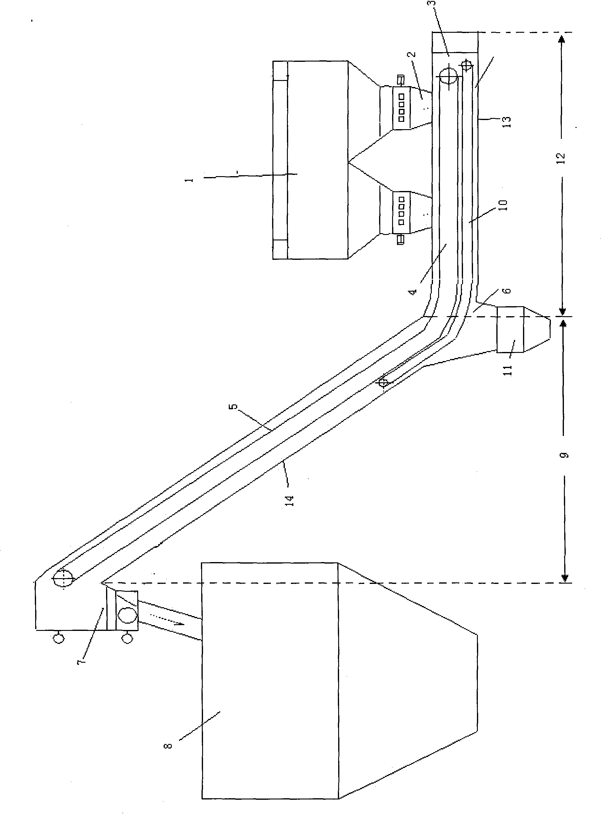
[0044] in such as figure 1 In the shown dry slag conveying equipment, the slag conveying device is a steel belt slag conveying device 4 , and the fine ash removal device is a scraper ash removing device 10 .

[0045] The above-mentioned dry slag conveying equipment includes a slag carrying box 3 and a steel belt slag conveyor 4 arranged in the slag carrying box 3; composition. The slag collection section 12 is arranged below the slag discharge port 2 of the boiler 1, and one end close to the slag discharge port 2 is closed, and the other end communicates with the slag lifting section 9, and the slag lifting section 9 is connected with the slag collection section 12 A slag outlet 7 is provided at the corresponding other end of one end, and a fine ash outlet 6 is provided at the end where the slag collecting section 12 is connected with the slag lifting section 9 . In the slag carrying box 3, and between the steel belt slag conveyor 4 and the carrying surface of the slag carry...

Embodiment 2

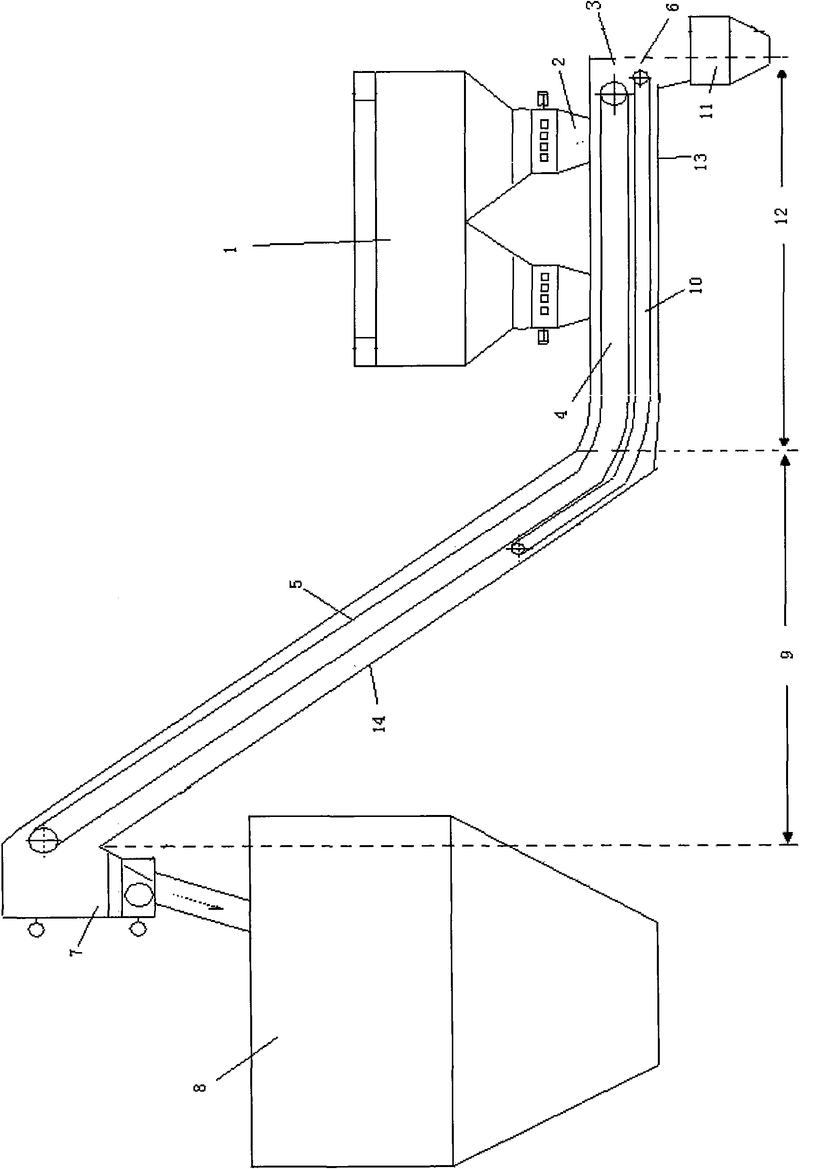
[0050] like figure 2 As shown, the difference between the dry slag conveying equipment in this embodiment and the dry slag conveying equipment in Embodiment 1 is that the fine ash outlet 6 is set in the slag collecting section 12 close to the slag outlet 2 of the boiler 1 At one end, the scraper ash removal device 10 moves toward the fine ash outlet 6, and the fine ash can be discharged through the fine ash outlet 6 into the mixing bin 11 provided at the fine ash outlet 6.

[0051] In addition to the structures described in the above two embodiments, the dry slag conveying equipment described in the present invention can also be modified so that both ends of the slag collection section 12 mentioned in Embodiment 1 and Embodiment 2 are simultaneously provided with There are fine ash outlets 6, and the scraper ash removal device moves towards at least one of the fine ash outlets.

[0052] The two ends of the slag collection section of the slag carrying box are provided with fi...

Embodiment 3

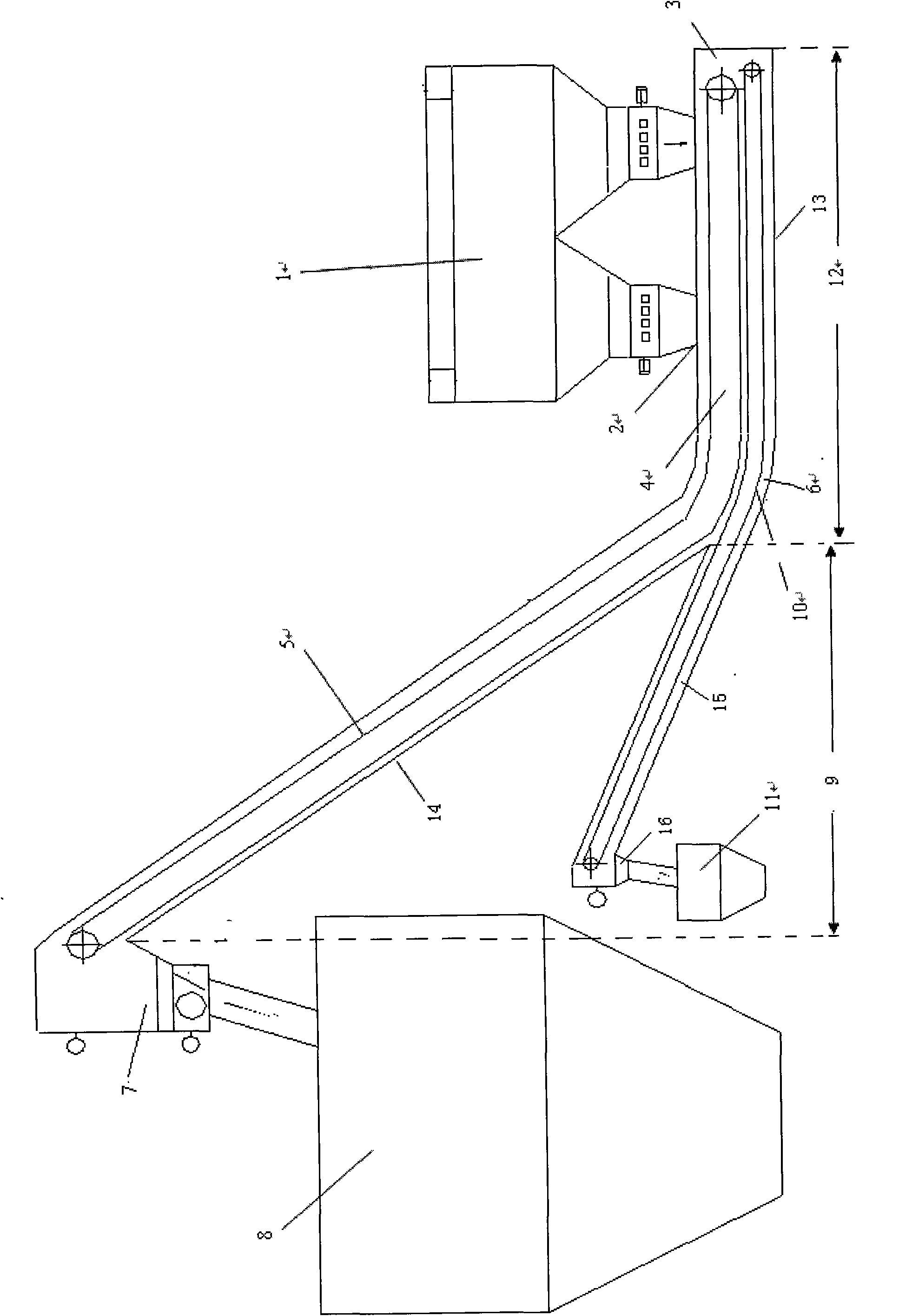
[0054] like image 3 The shown dry slag conveying equipment includes a slag carrying box 3 and a steel belt slag conveyor 4 installed in the slag carrying box 3; wherein, the slag carrying box 3 is lifted by the slag collecting section 12 and the slag Segment 9 is composed. The slag collection section 12 is arranged below the slag discharge port 2 of the boiler 1, and one end close to the slag discharge port 2 is closed, and the other end communicates with the slag lifting section 9, and the slag lifting section 9 is connected with the slag collection section 12 A slag outlet 7 is provided at the corresponding other end of one end, and a fine ash outlet 6 is provided at the end where the slag collecting section 12 is connected with the slag lifting section 9 . In the dry slag conveying equipment, there is also an extension box 15 with one end connected to the slag collection section 12 through the fine ash outlet 6, and the other end of the extension box 15 is provided with a...


PUM


Abstract

The invention relates to a dry-type slag-conveying device comprising a slag-bearing box body, a slag-conveying device and a fine ash removing device, wherein the slag-bearing box body consists of a slag collecting section and a slag lifting section which is connected with the slag collecting section and is positioned above the slag collection section; one connected end of the slag lifting sectionand the slag collecting section is provided with a coarse slag outlet; at least any of the two ends of the slag lifting section is provided with a fine ash outlet; and the fine ash removing device moves towards the direction of at least one fine ash outlet. The dry-type slag-conveying device effectively avoids the problem of the residual fine ash in the lifting section in the process of discharging the fine ash carried by the slag removing device through the slag lifting section, simultaneously also reduces the whole conveying load of the equipment and saves energy.

Description

technical field [0001] The invention relates to a boiler slag discharge device, in particular to a dry slag conveying device. Background technique [0002] To carry out dry slag discharge treatment for coal-fired boiler ash, it is necessary to discharge the boiler ash (including large ash and fine ash) from the bottom of the boiler, lift the discharged ash to a high position, and place it in the slag storage bin . At present, the dry slag conveying equipment mainly includes a slag carrying box and a steel belt slag conveying machine arranged in the slag carrying box. Wherein, the slag carrying box is divided into a slag lifting section and a slag collecting section; when the above slag discharge equipment is in operation, the ash discharged from the bottom of the boiler falls on the steel belt slag conveyor installed in the slag collecting section, and then passes through The slag lifting section is sent into the slag storage bin. [0003] Due to the air circulation in th...

Claims


Application Information

Patent Timeline
IPC IPC(8): F23J1/06
Inventor 刘振强张晶王玉玮夏春华张华兰吴瞳昕
Owner BEIJING GUODIAN FUTONG SCI & TECH DEV
Why Eureka
Try Eureka