
Liquid crystal light attenuation device

A light attenuation and liquid crystal technology, applied in optics, nonlinear optics, instruments, etc., can solve problems such as difficulties, affecting the contrast of light attenuation devices, and difficult to change directions

Active Publication Date: 2011-04-13
KUSN INFOVISION OPTOELECTRONICS
View PDF0 Cites 0 Cited by
  • Summary
  • Abstract
  • Description
  • Claims
  • Application Information

AI Technical Summary

Problems solved by technology

On the one hand, since the response time of the TN-type liquid crystal cell is proportional to the square of the cell thickness, although reducing the cell thickness of the liquid crystal cell can speed up the response speed of the liquid crystal light attenuation device, in general, the TN-type liquid crystal cell is suitable for modulation in the visible light band , if the modulation wavelength is in the mid-to-far infrared band, the response time will increase dozens of times, and the thickness of the liquid crystal cell cannot be reduced without limit. This solution has limited improvement in response speed, and the reduction in thickness will bring On the other hand, the ferroelectric liquid crystal light attenuation device currently has the following problems: (1) The arrangement and orientation of the ferroelectric liquid crystal needs to be coated with an alignment layer material on the surface of the glass substrate with electrode patterns , the arrangement and orientation of ferroelectric liquid crystal molecules is controlled by rubbing orientation, and due to the molecular characteristics of ferroelectric liquid crystal itself, it is very difficult to achieve uniform orientation; (2) the thickness of the liquid crystal cell of surface-stabilized ferroelectric liquid crystal is very small (usually 2um) , it is difficult to be suitable for the application of long-wavelength light attenuation devices; (3) ferroelectric liquid crystals are prone to alignment defects when they are impacted by external forces, and this defect is irreversible; (4) when the ferroelectric liquid crystal is applied to another angle, due to The role of anchoring energy, the transition layer liquid crystal close to the surface of the alignment layer is not easy to change direction, which affects the contrast of the light attenuation device

Method used


Image

  • Liquid crystal light attenuation device
  • Liquid crystal light attenuation device
  • Liquid crystal light attenuation device

Examples


Embodiment 1

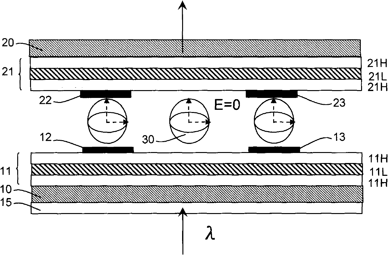
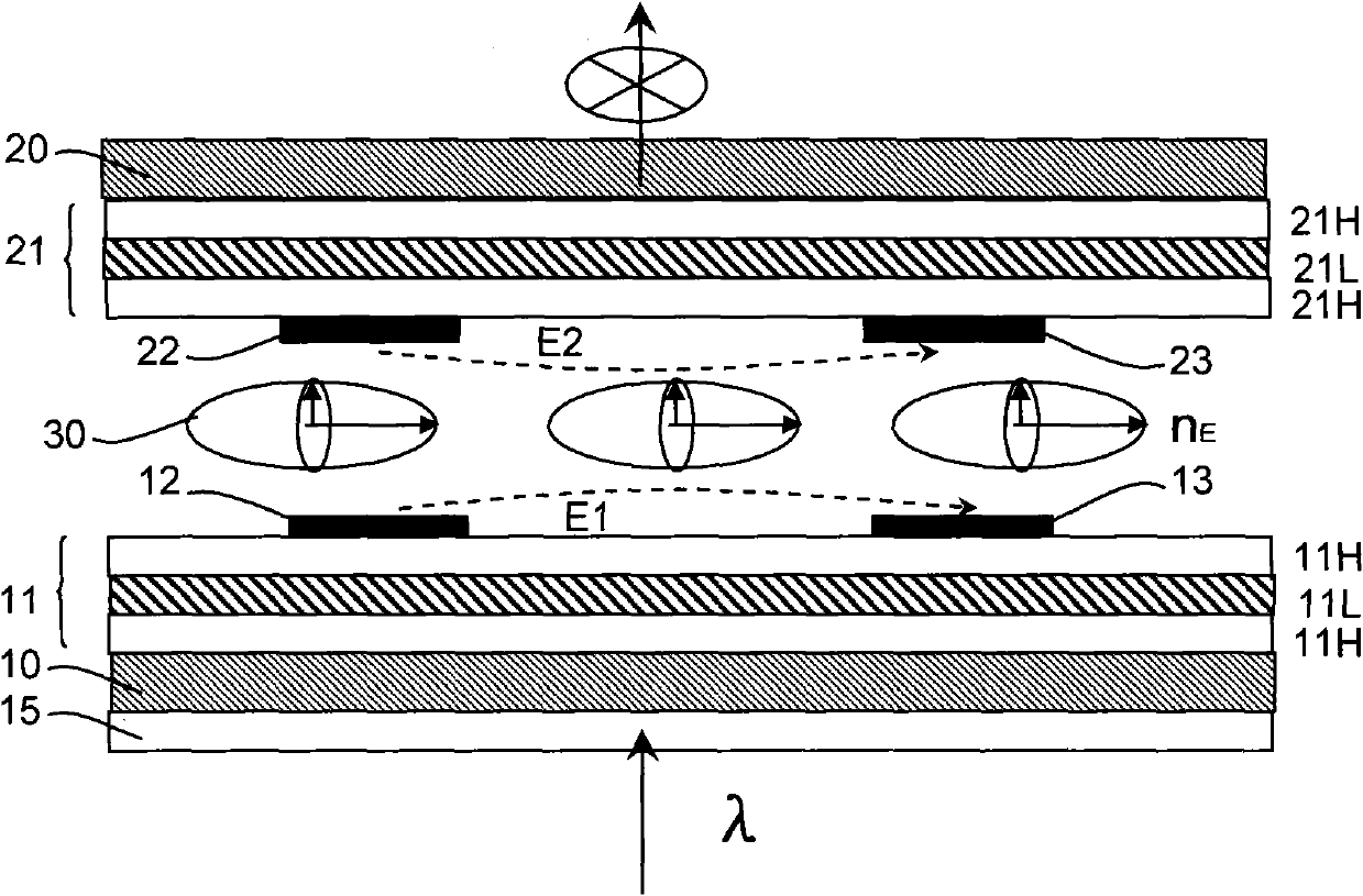
[0038] figure 1 with figure 2 This is a schematic diagram of the structure of the liquid crystal light attenuation device in this embodiment. among them, figure 1 Indicates that the liquid crystal light attenuation device is in the on state, figure 2 Indicates that the liquid crystal light attenuation device is in the off state. In order to highlight the characteristics of the present invention, parts that are necessarily directly related to the inventive point of the present invention are not shown in the drawings, such as sealant, spacers, etc.

[0039] Reference Figure 1-2 As shown, the liquid crystal light attenuation device includes:

[0040] A first substrate 10 and a second substrate 20 disposed oppositely;

[0041] The liquid crystal layer 30 enclosed between the first substrate 10 and the second substrate 20, and the liquid crystal layer 30 has the characteristic of converting an isotropic refractive index into an anisotropic refractive index under the action of an elec...

Embodiment 2

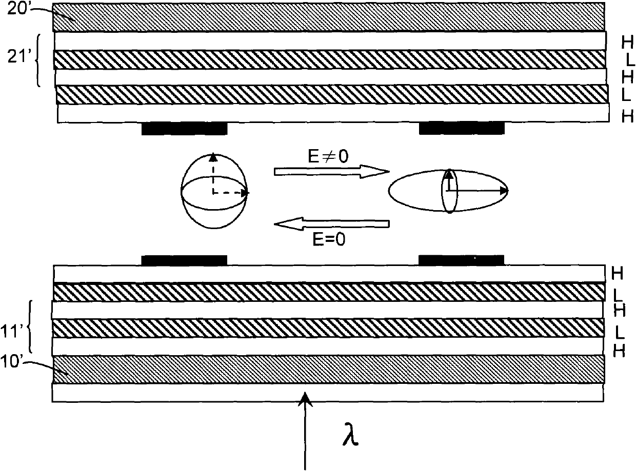
[0082] image 3 This is a schematic diagram of the structure of the liquid crystal light attenuation device in this embodiment. The figure shows the conversion process between the on state and the off state.

[0083] Such as image 3 As shown, the difference between this embodiment and the first embodiment is that the first reflective layer 11' and the second reflective layer 21' include a film system composed of five optical films with the same structure. The refractive index thin film layers and the low refractive index thin film layers are alternately stacked and arranged, with H representing the high refractive index thin film layer, and L representing the low refractive index thin film layer. The order of the film system in this embodiment is HLHLH. The five-layer film HLHLH on the first substrate 10' and the five-layer film HLHLH on the second substrate 20' together constitute the reflective film of this embodiment. Among them, the material of the high refractive index mat...


PUM

PropertyMeasurementUnit
refractive indexaaaaaaaaaa

Abstract

The invention provides a liquid crystal light attenuation device. The light attenuation device comprises a first substrate and a second substrate which are arranged face to face, a liquid crystal layer sealed between the first substrate and the second substrate, a first reflecting layer arranged on one side of the first substrate toward the liquid crystal layer, a second reflecting layer arrangedon one side of the second substrate toward the liquid crystal layer, first common electrodes and first control electrodes which are arranged on one side of the first reflecting layer toward the liquid crystal layer and second common electrodes and second control electrodes which are arranged on one side of the second reflecting layer toward the liquid crystal layer, wherein the liquid crystal layer has the property that under an electric field, the isotropic refractivity can be converted to the anisotropic refractivity, the first common electrodes and first control electrodes are arranged alternately, the second common electrodes and second control electrodes are arranged alternately, the second control electrodes are opposite to the first control electrodes, and the second common electrodes are opposite to the first common electrodes. The liquid crystal light attenuation device can increase the response speed.

Description

Technical field [0001] The present invention relates to the field of liquid crystal technology, in particular to a liquid crystal light attenuation device. Background technique [0002] In recent years, the rapid development of liquid crystal technology has promoted its wider application in the fields of flat panel displays, light attenuation devices, and variable wavelength filters. At present, the most commonly used liquid crystal light attenuation device uses twisted nematic (TN) type liquid crystal, but the response speed of TN type liquid crystal is very slow, usually tens of milliseconds, which limits the application of liquid crystal light attenuation devices . [0003] The following two solutions are adopted in the prior art to improve the response speed of the liquid crystal light attenuation device: [0004] (1) Reducing the thickness of the liquid crystal cell of the TN-type liquid crystal light attenuation device can make the response speed of the light attenuation devi...

Claims


Application Information

Patent Timeline
Patent Type & Authority Patents(China)
IPC IPC(8): G02F1/1333G02F1/133G02F1/1343
Inventor 崔宏青
Owner KUSN INFOVISION OPTOELECTRONICS
Learn More