Check patentability & draft patents in minutes with Patsnap Eureka AI!

Over current protection device

A protection device and overcurrent technology, applied in the direction of electric thermal protection switch, protection switch operation/release mechanism, etc., can solve the problems of difficult working conditions, inseparability, and complex structure of the second bimetallic contact piece, and achieve simple structure and easy operation. Easy assembly and design

Inactive Publication Date: 2010-03-03
SANYO ELECTRIC CO LTD
View PDF2 Cites 0 Cited by
  • Summary
  • Abstract
  • Description
  • Claims
  • Application Information

AI Technical Summary

Problems solved by technology

Therefore, it is difficult to set working conditions such as the force of the second bimetallic link, and the structure is also complicated.
In addition, since the movable contact is mechanically and forcibly separated from the fixed contact, there may be cases where the separation cannot be achieved if the fusion is strong.

Method used


Image

  • Over current protection device
  • Over current protection device
  • Over current protection device

Examples


Embodiment 1

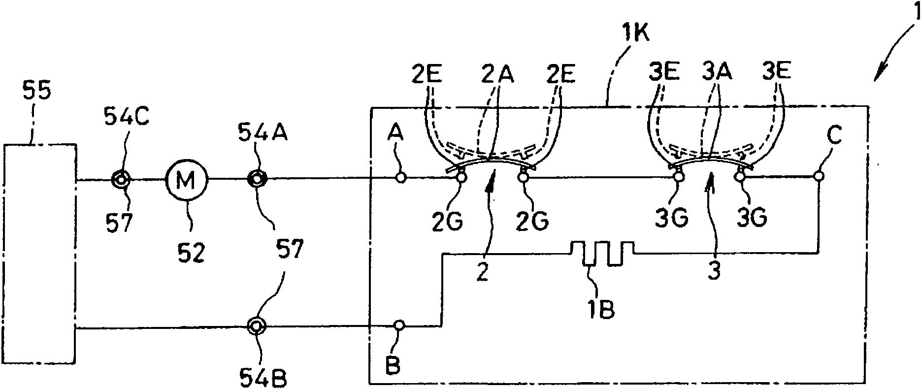
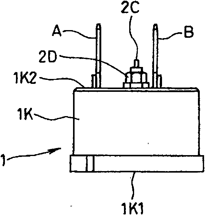
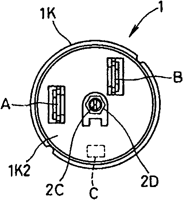
[0051] figure 1 It is a circuit diagram in which the first overcurrent relay unit and the second overcurrent relay unit constituting the overcurrent protection device of the present invention are connected in series; figure 2 It is a side view showing the appearance of the overcurrent protection device of the present invention; image 3 yes means figure 2 A diagram of the external appearance of the terminal part side of the shown overcurrent protection device; Figure 4 From figure 2 The internal composition diagram seen from the opening surface of the overcurrent protection device shown; Figure 5 It is a figure which shows the state which accommodated the overcurrent protection device of the present invention in the cover (cover), and was installed on the upper surface of the closed machine box of the electric compressor; Image 6 It is a specific exploded perspective view of the part where the overcurrent protection device of the present invention is accommodated in ...


PUM


Abstract

An over current protection device that surely prevents a burnout by opening a power supply circuit to an electric compressor upon an over current, includes a heater which generates heat by a current flowing through the electric compressor, a first over current relay unit which is serially connected to the heater, is thermoelectrically coupled thereto, and includes a first bimetal contact piece which opens a first contact at a temperature equal to or more than a first temperature, and recovers the first contact at a temperature lower than the first temperature and higher than 0 DEG C, and a second over current relay unit which is serially connected to the heater, is thermoelectrically coupled thereto, and includes a second bimetal contact piece which opens a second contact at a temperatureequal to or higher than a second temperature higher than the first temperature, and recovers the second contact only at a temperature lower than 0 DEG C, where both the first over current relay unit and the second over current relay unit open the power supply circuit to the electric compressor.

Description

technical field [0001] The invention relates to an overcurrent protection device for protecting electric compressors used in cooling equipment such as refrigerators and small air conditioners from being burnt out by overcurrents generated in overloaded or locked states. Background technique [0002] In the past, in order to protect the electric compressors used in cooling equipment such as refrigerators and small air conditioners in the overcurrent state, a device that is installed close to the body box of the electric compressor, senses the temperature, and utilizes a motor that flows through the electric compressor A bimetal device (bimetal) that operates by the heat of an electric heater (heater) that generates heat due to overcurrent, and an overcurrent protection device that opens and closes the switch tabs connected in series is installed between the motor of the electric compressor and the power supply. In this case, if the operating temperature of the bimetallic devi...

Claims


Application Information

Patent Timeline
IPC IPC(8): H01H71/16H01H81/02
Inventor 小林正英
Owner SANYO ELECTRIC CO LTD
Features
  • R&D
  • Intellectual Property
  • Life Sciences
  • Materials
  • Tech Scout
  • Unparalleled Data Quality
  • Higher Quality Content
  • 60% Fewer Hallucinations
Learn More