Method for compensating image dithering of airborne imaging equipment

A compensation method and image technology, which is applied in the field of electronics, can solve problems such as large amount of calculation, high hardware configuration requirements, complex algorithms, etc., and achieve the effect of small calculation workload and improved stability effect

Inactive Publication Date: 2010-03-03
CHANGCHUN UNIV OF SCI & TECH +1
View PDF5 Cites 25 Cited by
  • Summary
  • Abstract
  • Description
  • Claims
  • Application Information

AI Technical Summary

Problems solved by technology

Although the existing electronic image stabilization algorithm can perform real-time compensation, the algorithm is often complicated, the calculation amount is large, and the requirements for hardware configuration are high.

Method used


Image

  • Method for compensating image dithering of airborne imaging equipment

Examples


Embodiment Construction

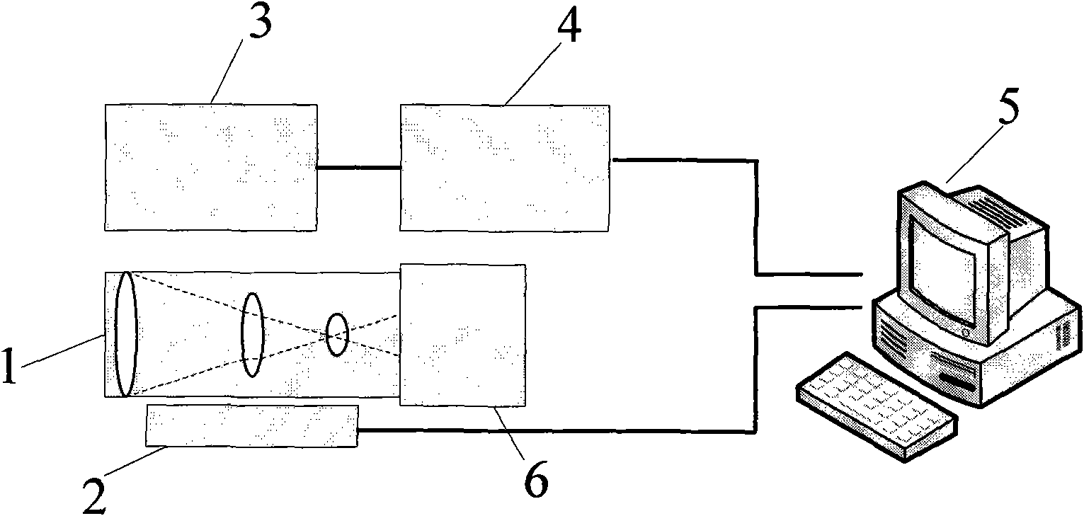
[0015] Adopt biaxial flexible rate gyroscope (3) to measure the boresight angular vibration velocity ωx, ωy of CCD camera (6) in real time, through integrator (4) diagonal vibration velocity ωx, ωy integration obtains angular displacement ψ-x and ψy, At the same time, the actual used focal length S is measured in real time by a displacement sensor (2) on the optical system of the airborne imaging device. Send the obtained image angular displacement ψx, ψy and focal length S to the computer processing unit (5), calculate the image displacement values ​​δX and δY in the X direction and Y direction, and translate the frame image along the X direction and Y direction by -δX Compensate the image with -δY to remove the influence of vibration on the image and obtain a stable image.


PUM


Abstract

The invention provides a method for compensating imaging dithering of airborne imaging equipment. The method adopts a rate gyroscope to measure the angular speed of the visual axis of a CCD camera inreal time, obtains the angular displacement of the visual axis by using an integrator for integration, measures the practical using focus of an optical zooming system by a displacement sensor, obtainsthe image displacement value of the CCD camera at the image surface due to the dithering by the calculation of a computer processing unit, and carries out reverse compensation to the image. The method has simple structure and brief algorithm, reduces calculation workload, inhibits the dithering of the image and improves the quality of the video image.

Description

technical field [0001] The invention relates to an image shake compensation method of an airborne imaging device, which belongs to the technical field of electronics. It is mainly used to compensate the image jitter caused by the vibration of the airborne imaging equipment, so as to ensure the quality of the continuous playback of the picture. Background technique [0002] When high-voltage power line inspection, personnel search and rescue, forest fire prevention inspection, air traffic command, etc. need to use airborne imaging equipment to observe ground scenery, the vibration of the aircraft will affect the stability of the picture, resulting in a decrease in the quality of the image during continuous playback. Although the use of the stabilizer pod can stabilize the boresight of optical imaging equipment to a certain extent, the vibration suppression residual still has a serious impact on the image clarity, especially for high-resolution images. Electronic image stabil...

Claims


Application Information

Patent Timeline
Patent Type & Authority Applications(China)
IPC IPC(8): H04N5/232G01M11/02G01P9/00
Inventor 张立中孟立新张仲先许金凯王城刚佟首峰韩冬刘智赵明亮丁莹金珈成别怀森
Owner CHANGCHUN UNIV OF SCI & TECH
Why Eureka
Try Eureka