Laser and video real-time coaxial correction system and method

An optical system and laser technology, applied in the direction of using optical devices, measuring devices, instruments, etc., can solve the problems of real-time changes in the optical path and the inability to extract the orientation in real time, so as to reduce the impact, reduce the data error rate, and increase the target power. Effect

Inactive Publication Date: 2020-04-28
NO 717 INST CHINA MARINE HEAVY IND GRP
View PDF6 Cites 2 Cited by
  • Summary
  • Abstract
  • Description
  • Claims
  • Application Information

AI Technical Summary

Problems solved by technology

Since the laser spot is a bright spot, when the laser is emitted, if the bright spot is near the target (UAV), the target will be completely covered, and the two directions cannot be extracted in real time, so this method is only applicable to the two optical axes respectively Calibration
Unable to adapt to the situation that the environment such as vehicle, airborne, strong wind etc. is greatly affected, and the optical path will change in real time

Method used


Image

  • Laser and video real-time coaxial correction system and method
  • Laser and video real-time coaxial correction system and method

Examples


Embodiment 1

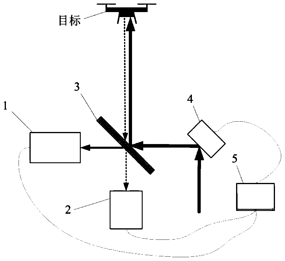
[0037] like figure 1 Shown is a schematic structural view of an embodiment of a laser and video real-time coaxial correction system provided by the present invention, figure 1 In , the solid line with arrows indicates the laser optical path, the dotted line with arrows indicates the target imaging optical path, and the dotted line with arrows is the signal line. figure 1 It can be seen that the system includes: a laser optical axis monitoring unit 1 , a video unit 2 , a beam splitter unit 3 , a laser optical axis correction unit 4 and a control unit 5 .

[0038] The video unit 2 images the target video. Part of the laser light is emitted after passing through the beam splitter unit 3 , and the other part enters the laser optical axis monitoring unit 1 , and the laser optical axis monitoring unit 1 determines the position of the optical axis of the laser in real time.

[0039] Preferably, the beam splitter unit 3 is arranged on the optical path where the target enters the vid...

Embodiment 2

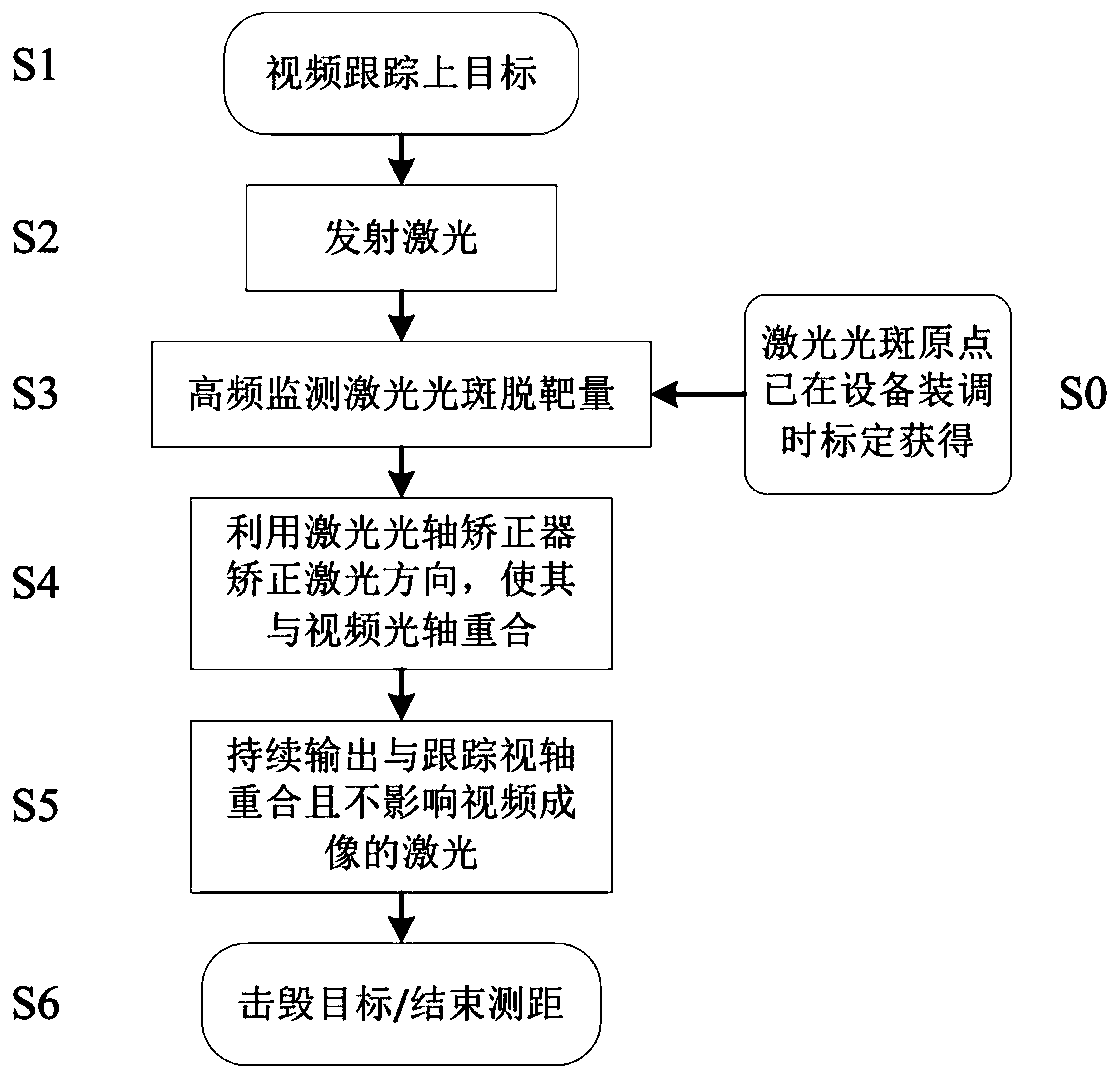
[0052] Embodiment 2 provided by the present invention is an embodiment of a laser and video real-time coaxial correction method provided by the present invention. The correction method is based on a correction system provided by the above-mentioned embodiments, such as figure 2 Shown is a flow chart of an embodiment of a laser and video real-time coaxial correction method provided by the present invention, consisting of figure 2 As can be seen, embodiments of the correction method include:

[0053] Step S1, tracking the target video unit 2 after finding the target.

[0054] Through the tracking servo system of the device, the video unit 2 can track the upper target.

[0055] Step S2, after entering into stable tracking, the laser emits high-energy or pulse ranging laser.

[0056] In step S3, the laser optical axis monitoring unit 1 monitors the real-time position of the optical axis of the laser and sends it to the control unit 5, and the control unit 5 calculates the devi...


PUM


Abstract

The invention relates to a laser and video real-time coaxial correction system and method. The system comprises a laser optical axis monitoring unit, a video unit, a spectroscope unit, a laser opticalaxis correction unit and a control unit. The video unit images a target video; one part of the laser is emitted after passing through the spectroscope unit, the other part of the laser enters the laser optical axis monitoring unit, and the laser optical axis monitoring unit calculates a real-time deviation value between an optical axis of the laser and a position of a laser optical axis adjustingorigin; the control unit calculates the deviation value between the real-time position of the optical axis of the laser and the position of the laser optical axis adjustment origin, and makes the laser optical axis correction unit adjust the optical axis direction of the laser according to the deviation value. Real-time compensation of a laser emission optical axis and a target tracking optical axis can be realized, a target arrival power of a high-energy laser during target hitting is effectively improved, a data error rate of laser tracking ranging equipment is effectively reduced, and an influence of external vibration and other factors on coaxiality of the optical axis during laser emission is decreased.

Description

technical field [0001] The invention relates to the technical field of beam control, in particular to a laser and video real-time coaxial correction system and method. Background technique [0002] The frequency of illegal use of low-cost flying objects such as drones and air balloons has been increasing in recent years, which has posed a great threat to human normal production, life, and collective activities. UAVs attack collective activities, oil fields, and power plants, carry substances that endanger public safety, and interfere with airport flights and other incidents continue to occur. The laser anti-drone system is a rapid defense system that uses lasers to strike targets (drones, air balloons, etc.). In order to achieve precise strikes on highly maneuverable targets, it is necessary to strictly ensure that the optical axis of laser emission coincides with the optical axis of target tracking. At the same time, in the field of national defense and security, the impr...

Claims


Application Information

Patent Timeline
Patent Type & Authority Applications(China)
IPC IPC(8): G01B11/26
CPCG01B11/26
Inventor 洪源李子龙杨晓燕张健
Owner NO 717 INST CHINA MARINE HEAVY IND GRP
Why Eureka
Try Eureka