Rotating and positioning structure of circuit board

A technology for positioning structures and circuit boards, which is applied to the installation of support structures, circuit layout on support structures, safety devices for installation boards, etc., and can solve problems such as slipping out of reed holes, falling off of circuit boards or main boards, and damage to the aforementioned components , to achieve the effect of solving the inconvenience of disassembly, avoiding damage and improving the force effect

Inactive Publication Date: 2010-03-03
NANTONG LUWAN ELECTRONICS
View PDF0 Cites 12 Cited by
  • Summary
  • Abstract
  • Description
  • Claims
  • Application Information

AI Technical Summary

Problems solved by technology

[0005] However, the above-mentioned positioning method adopting the gourd hole is positioned as a linear moving part, but the forces that the above-mentioned parts that need to be positioned with each other are all linear. At this time, because the positions where the parts are positioned with each other are stressed , so it is easy to cause damage to the aforementioned components
In addition, if the positioning is carried out by relying on the linear design of the gourd hole, when there is a force opposite to the direction of the force, the positioning post will easily slip out of the gourd hole, so that the circuit board or main board will fall off, causing serious consequences

Method used


Image

  • Rotating and positioning structure of circuit board
  • Rotating and positioning structure of circuit board
  • Rotating and positioning structure of circuit board

Examples


Embodiment Construction

[0030] Embodiments of the present invention are described below through specific examples, and those skilled in the art can easily understand other advantages and effects of the present invention from the content disclosed in this specification.

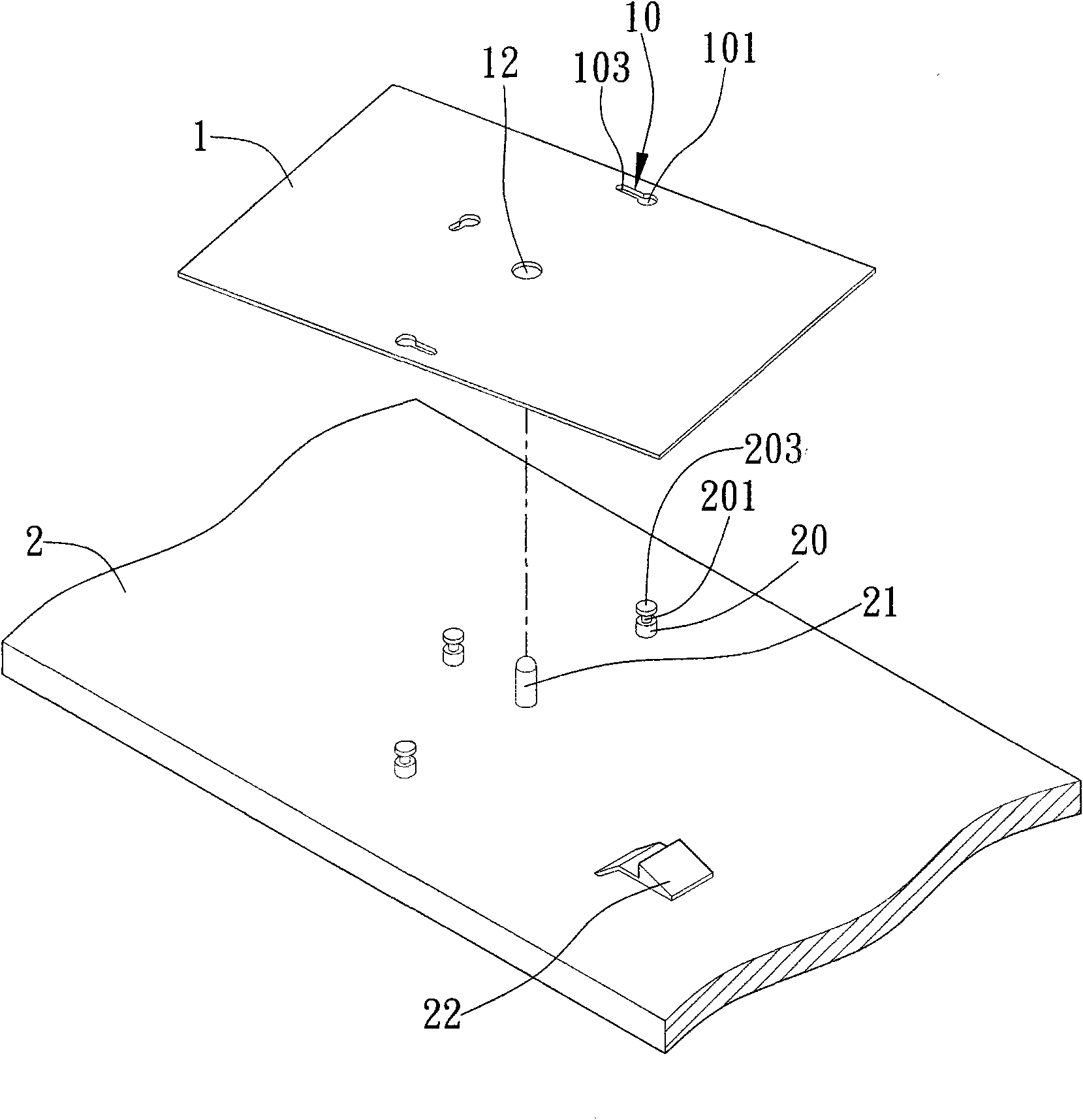
[0031] see figure 1 , is an exploded perspective view showing an embodiment of the circuit board rotation positioning structure of the present invention. It should be noted that the present invention is used to rotate a circuit board relative to a chassis bottom plate to make them mutually positioned. The following drawings are simplified schematic diagrams, which only illustrate the basic structure of the present invention in a schematic manner, so they only show The composition related to the present invention, and the displayed composition is not drawn according to the number, shape, and size ratio of the actual implementation. The number, shape, and size ratio of the actual implementation are a selective design, and its compositi...


PUM


Abstract

The inventions relates to a rotating and positioning structure of a circuit board, which is used for rotating the circuit board relative to a bottom board of a machine case and mutually positioning the circuit board and the bottom board. The circuit board is provided with a plurality of positioning holes; the bottom board of the machine case is provided with a plurality of corresponding positioning pillars; all the positioning holes are distributed on the circuit board by taking the same center of a circle, and each positioning hole is provided with a penetrating part and a positioning part; and each positioning pillar is provided with a head used for penetrating the penetrating part and a neck connected with the head and used for clamping the positioning part. The neck is clamped into thepositioning part by rotating the circuit board, so that the circuit board and the bottom board of the machine case are mutually clamped and positioned.

Description

technical field [0001] The invention relates to a circuit board rotation positioning technology, in particular to a rotation positioning structure of a rotation positioning circuit board and a chassis bottom plate. Background technique [0002] With the continuous development and improvement of science and technology, the design of products is developing towards the common goal of higher performance, better quality, more convenient use, and lower cost. In the design process, any improvement, as long as it is beneficial to improve the product Substantial improvements in performance, product quality, operator convenience, and product cost reduction are all inventions and creations with industrial utility value, and are also in line with the spirit of encouraging, protecting, and utilizing inventions and creations in the Patent Law. [0003] In all kinds of products, many components need to be positioned with each other, and the traditional positioning method generally adopts s...

Claims


Application Information

Patent Timeline
Patent Type & Authority Applications(China)
IPC IPC(8): H05K7/14H05K7/12G06F1/18
CPCH05K7/1417Y10T29/53174
Inventor 季平陈志丰
Owner NANTONG LUWAN ELECTRONICS
Why Eureka
Try Eureka