Drill jig for processing positioning holes of bead-fixed ring

A technology of positioning holes and drilling dies, which is applied to the drilling dies used for workpieces and other directions, can solve problems such as the influence of positioning hole machining accuracy.

Inactive Publication Date: 2010-03-10
WUJIANG SHUANGJING BEARING
View PDF0 Cites 0 Cited by
  • Summary
  • Abstract
  • Description
  • Claims
  • Application Information

AI Technical Summary

Problems solved by technology

The processing of the positioning hole needs to be completed with the help of a drilling machine and a drilling mold, and the drilling mold will inevitably affect the machining accuracy of the positioning hole diameter and hole distance

Method used


Image

  • Drill jig for processing positioning holes of bead-fixed ring
  • Drill jig for processing positioning holes of bead-fixed ring
  • Drill jig for processing positioning holes of bead-fixed ring

Examples


Embodiment 1

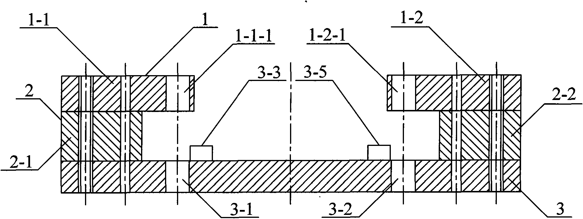
[0018] Such as figure 1 and figure 2 As shown, the drilling mold in this embodiment includes an upper mold 1 , a middle mold 2 and a lower mold 3 . The upper mold 1 is fixedly connected to the lower mold 3 through the middle mold 2 , and there is a space between the upper mold 1 and the lower mold 3 .

[0019] The upper mold 1 includes a first upper mold 1-1 and a second upper mold 1-2, and the middle mold 2 includes a first middle mold 2-1 and a second middle mold 2-2. The first upper mold 1-1 is connected to the left part of the lower mold 3 through the first middle mold 2-1 and by means of a pair of bolts and a pair of pins. Part of the first upper mold 1-1 is in contact with the first middle mold 2-1. On another part of the first upper die 1-1, a first upper die drill hole 1-1-1 is set. Similarly, the second upper mold 1-2 is connected to the right part of the lower mold 3 through the second middle mold 2-2 and by means of a pair of bolts and a pair of pins. Part of ...

Embodiment 2

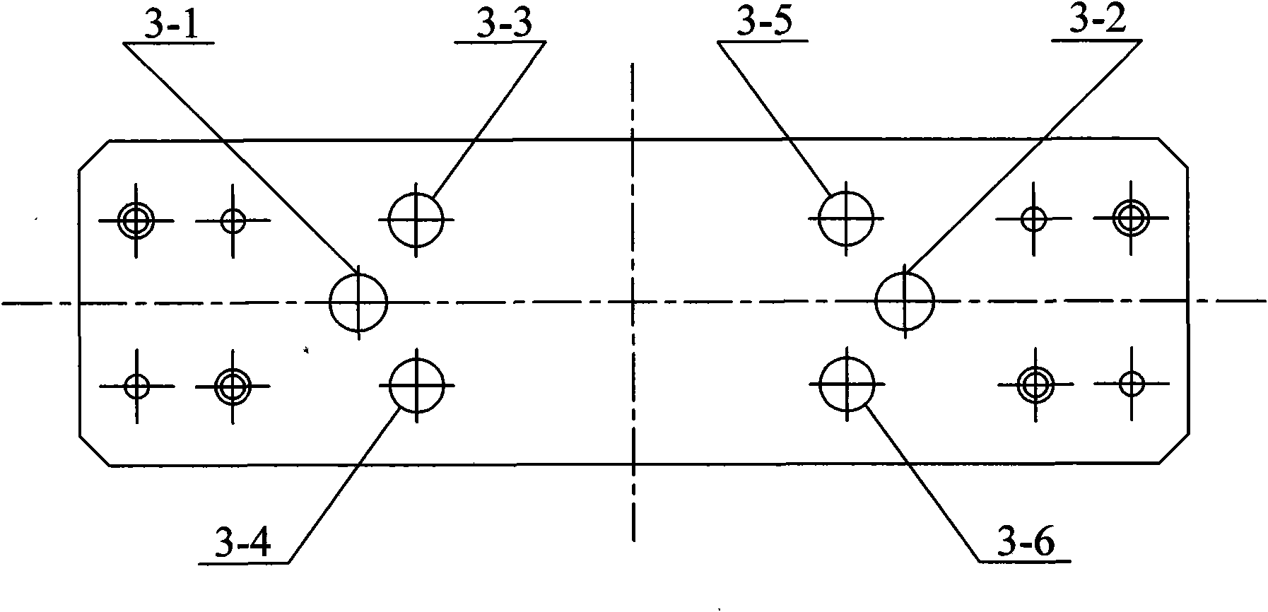
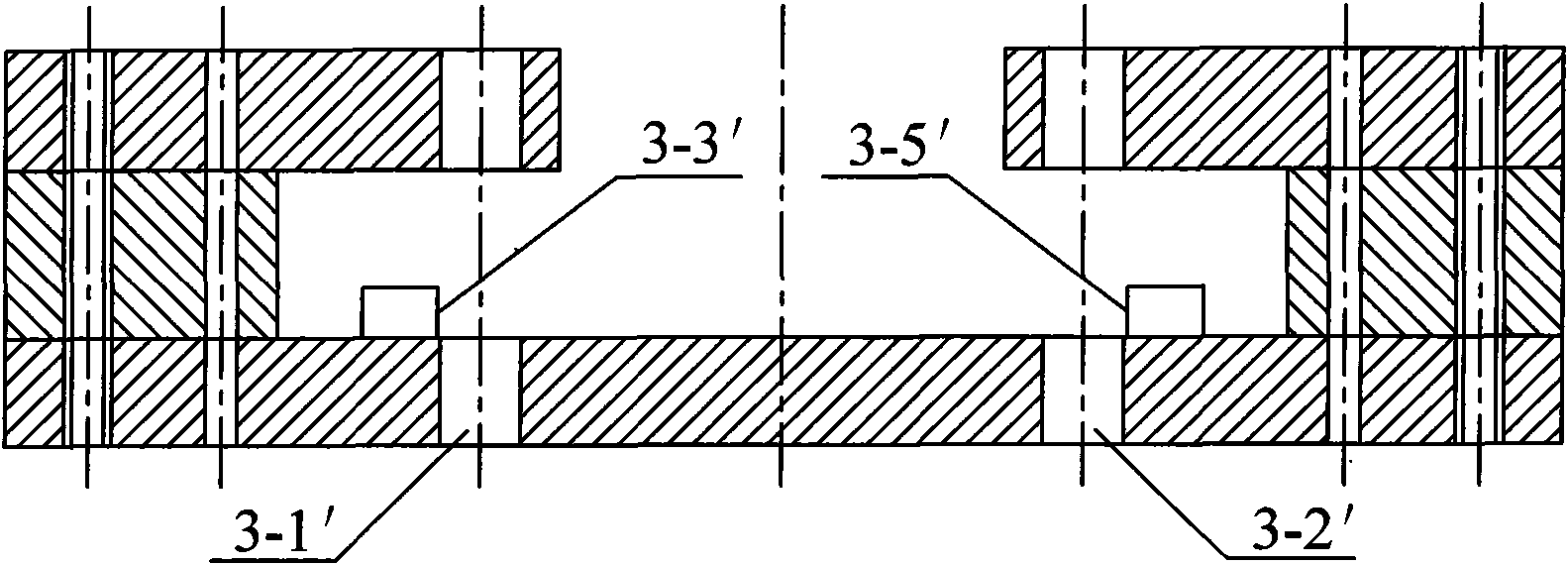
[0024] Such as image 3 and Figure 4 As shown, the structure of the jig in this embodiment is roughly the same as that in Example 1, the difference is that the two positioning pins 3-3' and 3-4' are farther away from the lower die than the hole 3-1' 3. The center line in the width direction is far; the other two positioning pins 3-5' and 3-6' are farther from the center line in the width direction of the lower die 3 than the drill hole 3-2, so as to meet the requirements of processing the rear positioning bead with two positioning holes. Circle requirements.

Embodiment 3

[0026] Such as Figure 5 , Figure 6 and Figure 7 As shown, the structure of the jig in this embodiment is substantially the same as the jig in Embodiment 1, except that the upper mold 4 is an integral structure. Four evenly distributed upper die drilling holes 4-1, 4-2, 4-3 and 4-4 are set in the middle part of the upper die 4. On the lower die 6, four lower die bores 5-1, 5-2, 5-4 corresponding to the above four evenly distributed upper die bores 4-1, 4-2, 4-3 and 4-4 3 and 5-4. In addition, four positioning pins 5-5, 5-6, 5-7 and 5-8 are set on the upper side of the lower mold 5, and the above four positioning pins 5-5, 5-6, 5-7 and 5-8 are distributed between two adjacent lower mold drilling holes.

[0027] The drilling jig in this embodiment is used to process the rear bead ring with four positioning holes.


PUM


Abstract

The invention discloses a drill jig for processing positioning holes of a bead-fixed ring. By using the drill jig to process positioning holes of the bead-fixed ring, the processing precisions of apertures and pitches of the positioning holes can be ensured. The drill jig comprises an upper mould, a middle mould and a lower mould, wherein the upper mould is fixedly connected with the lower mould through the middle mould; a space is left between the upper mould and the lower mould; the upper mould drill holes are arranged on the upper mould, and the lower mould drill holes corresponding to theupper mould drill holes are arranged on the lower mould; and a positioning pin is arranged at an upper side surface of the lower mould, which can be matched with a bead-fixed hole of the bead-fixed ring.

Description

technical field [0001] The invention relates to a mold for processing a bead ring, in particular to a drilling mold for processing a positioning hole of the bead ring. Background technique [0002] The diameter and distance of the positioning hole in the bead ring determine the position of the cone surface of the bead hole. The positioning hole is the benchmark for the subsequent drilling, reaming, boring and milling processes. Therefore, the machining accuracy of the positioning hole is very important to the product quality. Impact. The processing of the positioning hole needs to be completed by means of a drilling machine and a drilling template, and the drilling template will inevitably affect the machining accuracy of the aperture and pitch of the positioning hole. Contents of the invention [0003] The technical problem to be solved by the present invention is to provide a drilling jig for processing the positioning holes of the bead ring. Using the drilling jig to p...

Claims


Application Information

Patent Timeline
Patent Type & Authority Applications(China)
IPC IPC(8): B23B47/28
Inventor 俞立群张建荣
Owner WUJIANG SHUANGJING BEARING
Why Eureka
Try Eureka