Blade carrier replacing device of combined flying shear

A technology of combined flying shears and flying shears, which is applied to the attachment of shearing machines, devices for shearing forming blanks, shearing devices, etc., which can solve the problems of long time and high labor intensity of workers

Inactive Publication Date: 2010-03-10
BEIJING JINGCHENG RUIXINCHANGCAI ENG TECH
View PDF1 Cites 13 Cited by
  • Summary
  • Abstract
  • Description
  • Claims
  • Application Information

AI Technical Summary

Problems solved by technology

After the new tool holder is installed, it is necessary to adjust the gap between the cutting blades

Method used


Image

  • Blade carrier replacing device of combined flying shear
  • Blade carrier replacing device of combined flying shear
  • Blade carrier replacing device of combined flying shear

Examples


Embodiment Construction

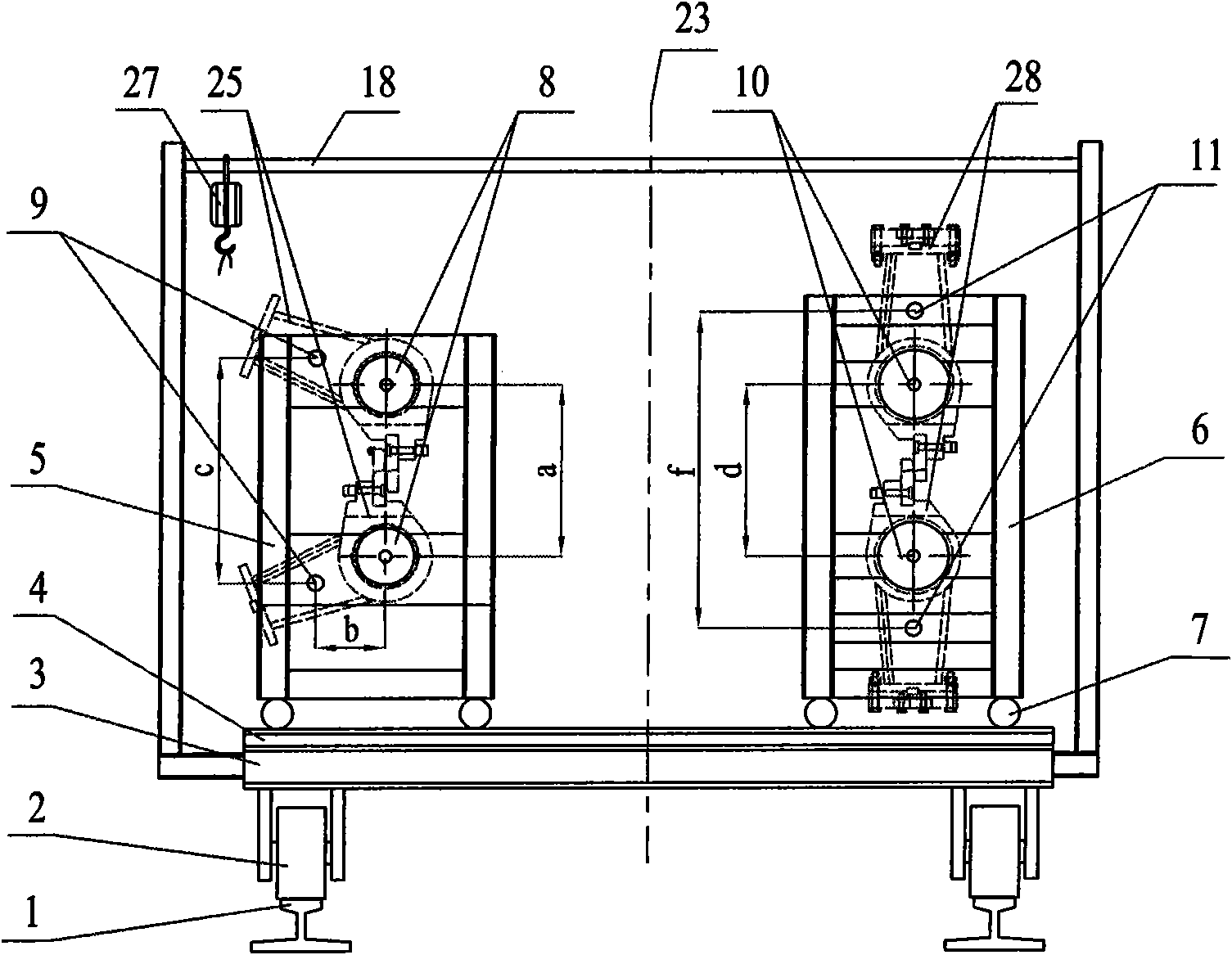
[0019] see figure 1 , the tool holder replacement device of the combined flying shear machine of the present invention includes a cart 3 walking on the ground track 1, a trolley walking track 4 is arranged on the chassis of the cart, and a useful track 4 is arranged on the trolley walking track 4 The trolley A 5 used for loading and unloading and adjusting the crank tool rest and the trolley B 6 for loading and unloading and adjusting the rotary tool rest.

[0020] Described trolley 3 comprises vehicle frame chassis, and the cart wheel 2 that is connected with chassis, is provided with trolley walking track 4 on chassis, and described trolley walking track 4 has the intermediate tool that aligns with the cutting center line of flying shears. Bit 23. At ordinary times, dolly first 5, dolly second 6 are positioned at the both sides of middle station 23 respectively, and when cart 3 was on the ground rail 1, this middle station 23 is aimed at the cutting center line of flying sh...


PUM


Abstract

The invention discloses a blade carrier replacing device of a combined flying shear, comprising a cart (3) which runs on a ground track (1), a trolley track (4) is arranged at the chassis of the cart,a trolley A (5) which is used for assembling and disassembling and adjusting a crank blade carrier and a trolley B (6) which is used for assembling and disassembling and adjusting a rotary blade carrier are arranged on the trolley track (4), a hanging bracket which is used for lifting a connecting rod which is separated from the crank blade carrier is arranged at the chassis of the cart. The blade carrier in the flying shear can be disassembled easily and can be replaced by a needed blade carrier easily without coordination of an overhead travelling crane, the operation time of replacing theblade carrier is reduced, the labor intensity is reduced. The reassembling and adjustment of location and shear blade side gap can be carried out to the disassembled blade carrier outside a rolling line, the time of adjusting equipment in a production line is saved, and the production efficiency is increased, thereby being beneficial to the safety production.

Description

technical field [0001] The invention relates to an auxiliary device of a combined flying shear, in particular to a quick replacement device for a tool holder of the combined flying shear. technical background [0002] Flying shears are devices used to cut rods or wires. Application number 200920175641.5 discloses a combined flying shear, which is equipped with two sets of tool holders, one set is a crank type tool holder, and the other is a rotary tool holder. When working, it is determined whether to use the crank shear mode or the rotary shear mode according to the size of the rolled piece to be sheared and the operating speed. When the crank shearing mode is adopted, a crank type knife rest is installed on the flying shear, and when the rotary shearing mode is required, a rotary knife rest is installed on the flying shear. When the cutting mode is switched, the knife holder needs to be replaced. The existing method of replacing the knife holder is to use the crane in th...

Claims


Application Information

Patent Timeline
IPC IPC(8): B23P19/04B23D25/08B23D33/00
Inventor 沈士蒽何巍巍李想
Owner BEIJING JINGCHENG RUIXINCHANGCAI ENG TECH
Why Eureka
Try Eureka