
Three-dimensional computerized numerical control sawing machine

A sawing machine, three-dimensional technology, applied in the field of three-dimensional CNC sawing machine, can solve problems such as constraints, achieve accurate and reliable synchronous transmission, and clean operating environment

Inactive Publication Date: 2010-03-10
高国强
View PDF7 Cites 20 Cited by
  • Summary
  • Abstract
  • Description
  • Claims
  • Application Information

AI Technical Summary

Problems solved by technology

An electric saw disclosed in the 99126412.6 patent, a multi-purpose sawing machine disclosed in the 02111758.6 patent, a pneumatic saw disclosed in the 02132230.9 patent, etc. These sawing machines are all hand-held tools; The sawing machine, the winding sawing machine disclosed in the 01239242.1 patent, the module cutting machine disclosed in the 01268623.9 patent, etc., all such sawing machines are hand-held to be processed and manually fed and pushed forward; the known sawing machines are only mechanical instead of manual sawing. It is not a real automation, it is still bound by manual skills and cannot get rid of the influence of human factors

Method used


Image

  • Three-dimensional computerized numerical control sawing machine
  • Three-dimensional computerized numerical control sawing machine
  • Three-dimensional computerized numerical control sawing machine

Examples


Embodiment Construction

[0060] The present invention will be further described below in conjunction with the accompanying drawings in the form of embodiments.

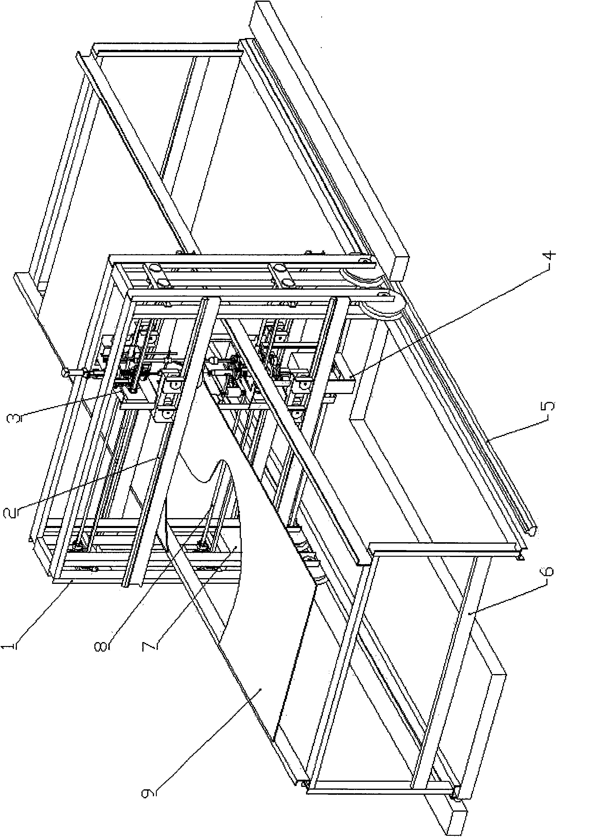
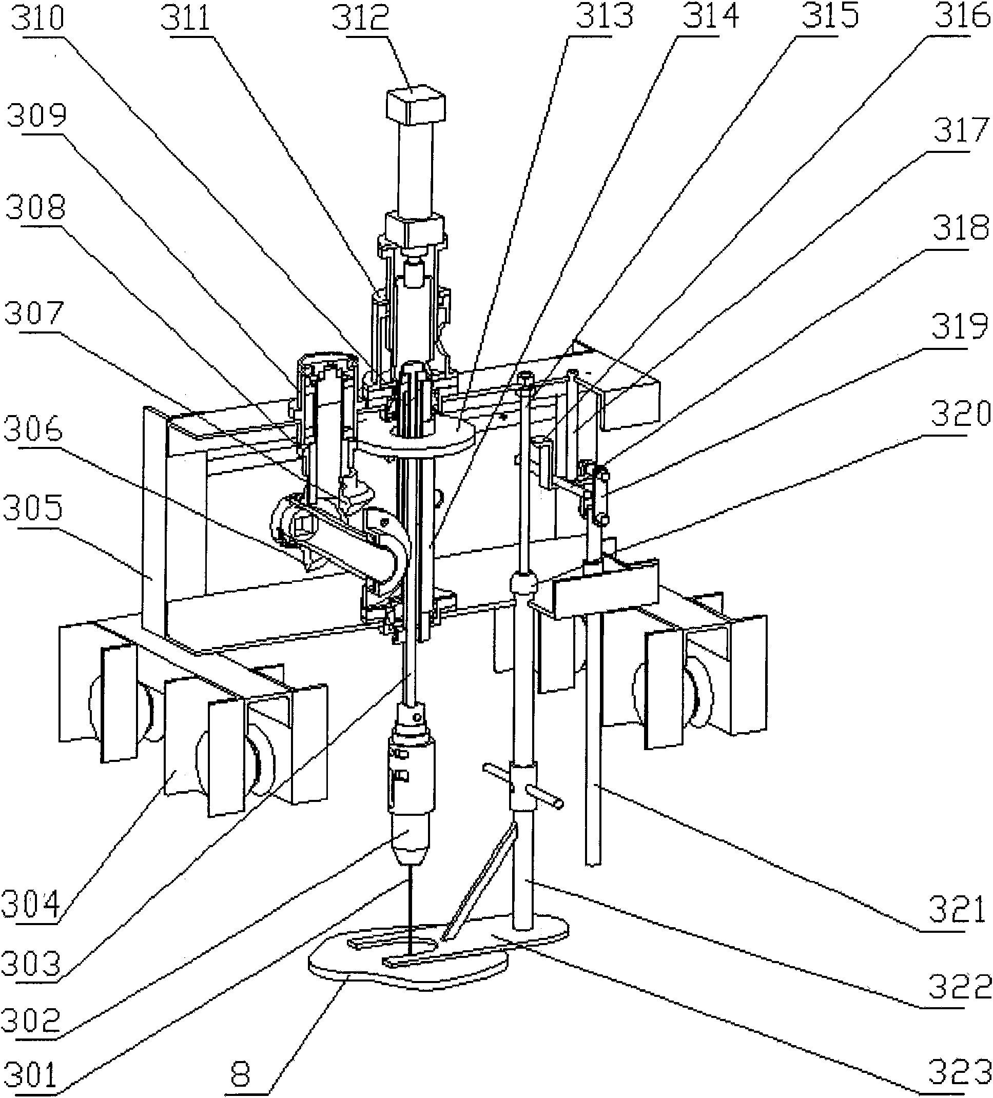
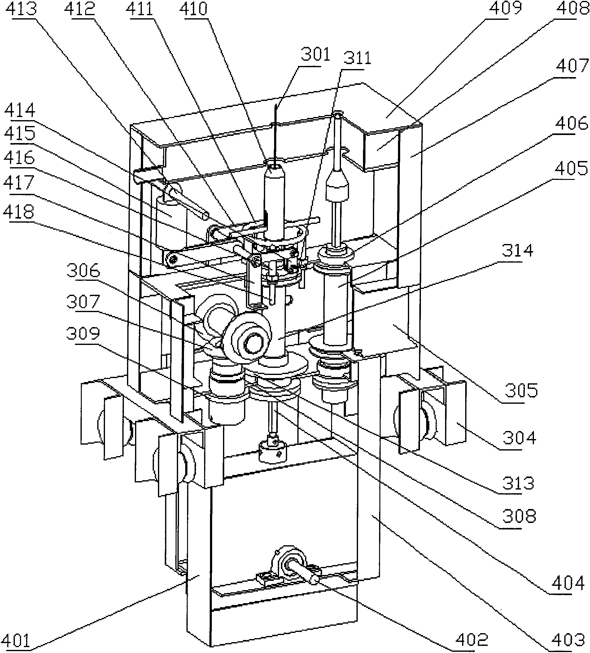
[0061] The frame 1 is connected by section steel into a rigid whole (can also be cast), the longitudinal guide rails 2 are installed on both sides of the frame 1, and the transverse guide rails 5 are fixedly installed under the frame 1 relative to the ground; the upper chassis 3 and the lower chassis 4 are respectively installed on On the longitudinal guide rail 2, the workbench 6 straddles the hollow part of the frame 1 and is fixed between the upper chassis 3 and the lower chassis 4 relative to the ground (the horizontal guide rail 5 and the workbench 6 can be integrated), and the processed object 9 Fixed on the workbench 6, the saw blade 301 is installed between the upper chuck 302 of the upper chassis 3 and the lower chuck 410 of the lower chassis 4 and is tensioned; the electric control system 7 is installed on one side of the frame 1, an...


PUM


Abstract

The invention discloses a three-dimensional computerized numerical control sawing machine, which mainly comprises a frame (1), longitudinal guide rails (2), an upper machine box (3), a lower machine box (4), transverse guide rails (5), a worktable support (6), an electrical control system (7), a transmission system (8) and other parts, wherein the upper machine box (3) and the lower machine box (4) are arranged on rigid frame (1) to move along the longitudinal guide rails (2) under control and move together with the frame (1) as a whole along the transverse guide rails (5) under control; a power box (401) performs a reciprocating motion to draw a tightened saw blade (301) and rotates under control to ensure a saw cutting edge direction is consistent with a saw cutting operation direction;and three-dimensional motions are monitored by a displacement sensor and fed back to the electrical control system (7) to be treated by a computer in real time, and saw cutting tracks may be various complex plane geometrical curves.

Description

Technical field [0001] The invention relates to a sawing machine, in particular to a three-dimensional numerical control sawing machine. Background technique [0002] As we all know, the reciprocating motion of the saw blade can cut the processing object, and the sawing can be cut along the predetermined track to obtain various shapes of saw kerf. However, the traditional manual sawing operation is not only labor-intensive, but also the processing quality depends to a large extent on the level of manual skills. An electric saw disclosed in the 99126412.6 patent, a multi-purpose sawing machine disclosed in the 02111758.6 patent, a pneumatic saw disclosed in the 02132230.9 patent, etc. These sawing machines are all hand-held tools; The sawing machine, the winding sawing machine disclosed in the 01239242.1 patent, the module cutting machine disclosed in the 01268623.9 patent, etc., all of these sawing machines are hand-held to be processed and manually fed and pushed; the know...

Claims


Application Information

Patent Timeline
Patent Type & Authority Applications(China)
IPC IPC(8): B27B19/04B27B19/06
Inventor 高国强
Owner 高国强
Learn More