Even landing device of robot car body
A robot and car body technology, applied in the field of robots, can solve problems such as easy overturning and poor load capacity, and achieve the effects of convenient assembly and disassembly, increased load capacity, and guaranteed accuracy
Inactive Publication Date: 2011-01-05
ZHEJIANG UNIV
View PDF1 Cites 0 Cited by
- Summary
- Abstract
- Description
- Claims
- Application Information
AI Technical Summary
Problems solved by technology
The purpose of the present invention is to provide a robot car body uniform grounding device, which solves the problems of poor load capacity and easy overturning of the robot car body in the traditional three-wheel landing arrangement, and at the same time ensures that the wheels are evenly on the ground, improving the load capacity of the robot car body and stability
Method used
View moreImage
Smart ImageViewing Examples
Examples
Embodiment Construction
Login to View More PUM
 Abstract
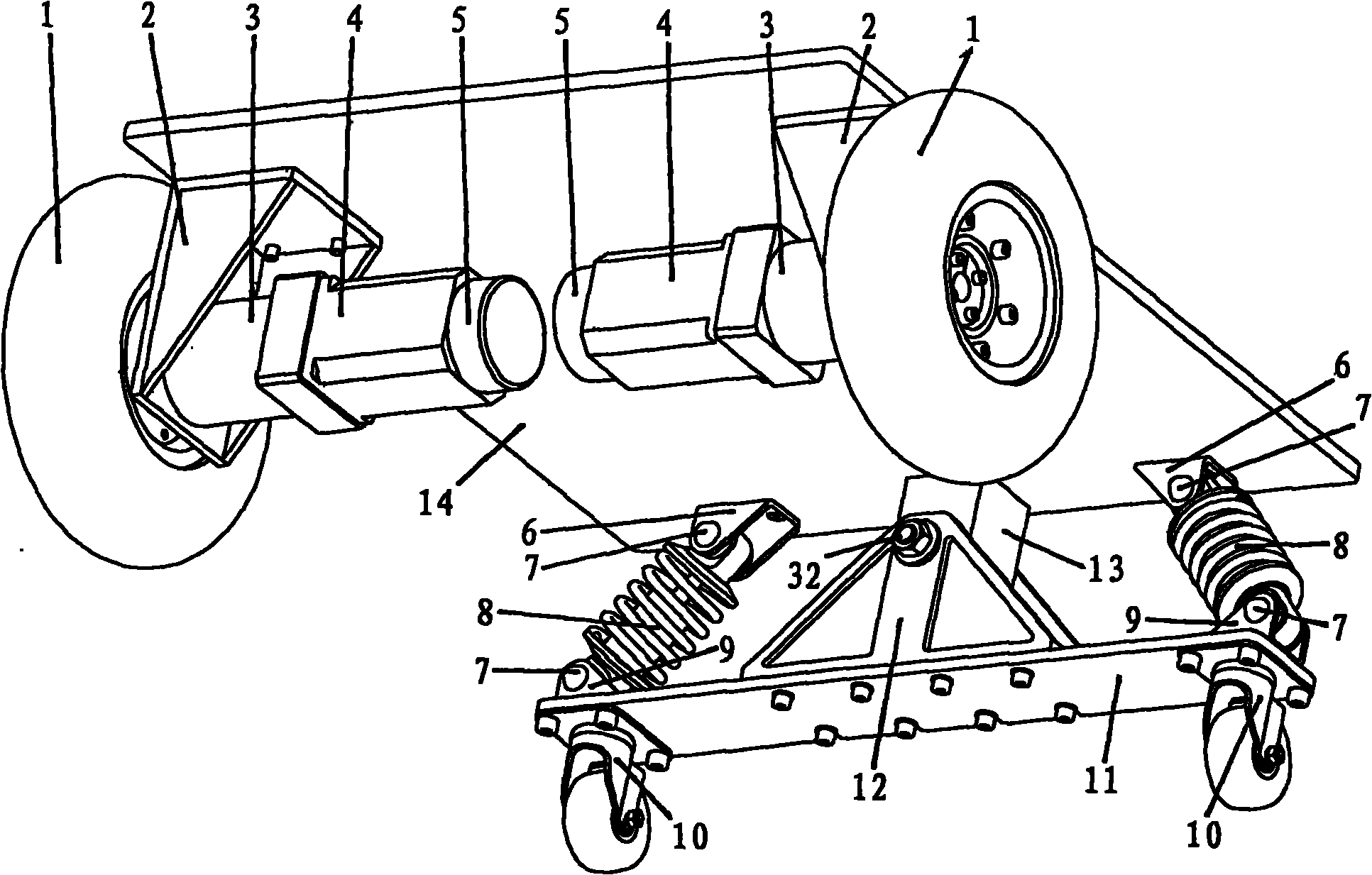
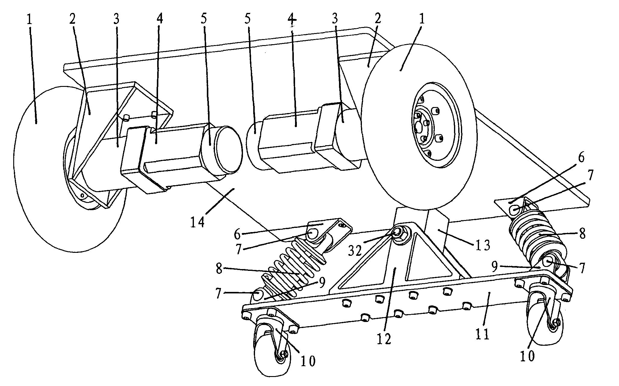
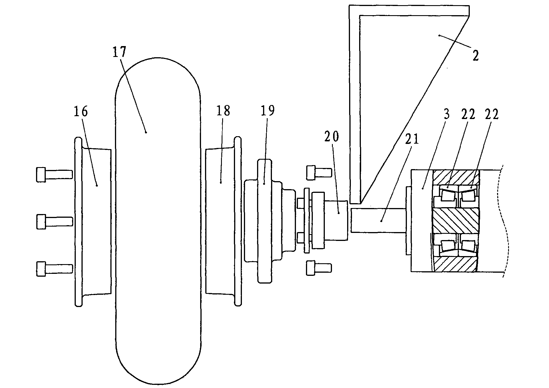
The invention discloses an even landing device of a robot car body. The eudipleural driving wheel unit of the invention respectively comprises a driving wheel, a driving wheel bracket, a coder arranged on a motor, a reducer and a motor, wherein the reducer and the motor are installed together; a self-balancing follower wheel unit comprises an upper bracket and a lower bracket of a shock absorber,the eudipleural shock absorber, an eudipleural follower wheel, a balance beam, two balance beam brackets and a bearing assembly; the reducer is fixedly installed on the driving wheel bracket, the driving wheel is fixed on the output shaft of the reducer, and the driving wheel bracket is fixed on a bottom plate; two follower wheels are arranged on two ends of the balance beam, and two ends of the shock absorber are movably connected with the upper bracket and the lower bracket of the shock absorber, and the upper bracket and the lower bracket of the shock absorber are correspondingly fixed on the bottom plate and the end part of the balance beam; the bearing assembly is arranged in the middle of the balance beam; and two balance beam brackets are respectively connected with the bearing assembly and the balance beam fixed on the bottom plate. The invention solves the problems of poor load capacity and easy overturning of the traditional robot car body and ensures that wheels can evenly land.
Description
A robot car body uniform grounding device technical field The invention belongs to the field of robots, and relates to a uniform landing device for a robot car body. Background technique A wheeled mobile robot using a two-wheel differential drive mechanism generally consists of two driving wheels and a follower wheel. This three-wheel landing method has a simple structure. Due to the "three-point coplanar" principle, all three wheels can evenly touch the ground. ; But the robot body that adopts this mechanism has the shortcomings of poor load capacity and easy overturning. If the number of follower wheels is increased to two, two drive wheels are installed on both sides of the front of the robot, and two follower wheels are installed on both sides of the rear, the load capacity and stability will be significantly improved; Otherwise, due to installation deviation and uneven road surface, the wheels will hang in the air, which will affect the stability of the car body and ...
Claims
Login to View More Application Information
Patent Timeline
 Patent Type & Authority Patents(China)
IPC IPC(8): B60G23/00
Inventor 舒畅熊蓉
Owner ZHEJIANG UNIV
Features
- R&D
- Intellectual Property
- Life Sciences
- Materials
- Tech Scout
- Unparalleled Data Quality
- Higher Quality Content
- 60% Fewer Hallucinations
Learn More Browse by: Latest US Patents, China's latest patents, Technical Efficacy Thesaurus, Application Domain, Technology Topic, Popular Technical Reports.
© 2025 PatSnap. All rights reserved.Legal|Privacy policy|Modern Slavery Act Transparency Statement|Sitemap|About US| Contact US: help@patsnap.com


