
Trickle type pure oxygen dissolving device

A pure oxygen and dissolved oxygen technology, applied in the field of oxygen dissolvers, can solve the problems of high manufacturing, installation, maintenance and price, high energy consumption of water circulation, and low oxygen utilization rate.

Inactive Publication Date: 2010-03-10
FISHERY MACHINERY & INSTR RES INST CHINESE ACADEMY OF FISHERY SCI
View PDF0 Cites 3 Cited by
  • Summary
  • Abstract
  • Description
  • Claims
  • Application Information

AI Technical Summary

Problems solved by technology

Conventional pure oxygen oxygenation methods include two types: direct release device (such as nano aeration disc, etc.) and pressure type water-air (oxygen) mixed aeration; Oxygenation is generally used for direct aeration in fish ponds. It has the advantages of simple equipment, low energy consumption and convenient use, but its oxygen utilization rate is low (generally 20% to 40%); Oxygen) mixed oxygenation is often used for oxygenation in the water treatment process. Although its oxygen utilization rate is quite high (generally greater than 90%) and the dissolved oxygen in the effluent is high (generally greater than 35mg / L), due to the pressure type water-gas (Oxygen) The mixing chamber (body) for mixing and increasing oxygen has a pressure of more than 0.1MPa when it works, causing the water body entering the mixing chamber to require a water body pressure greater than 0.1MPa, resulting in excessive water circulation energy consumption during the oxygenation process. In addition, Since the mixing chamber is a pressure vessel, its manufacturing, installation, maintenance and price are relatively high

Method used


Image

  • Trickle type pure oxygen dissolving device
  • Trickle type pure oxygen dissolving device

Examples


Embodiment

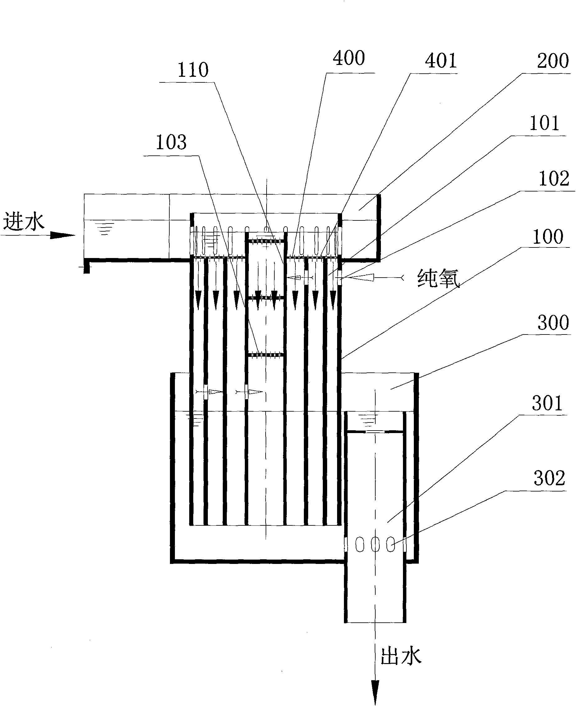
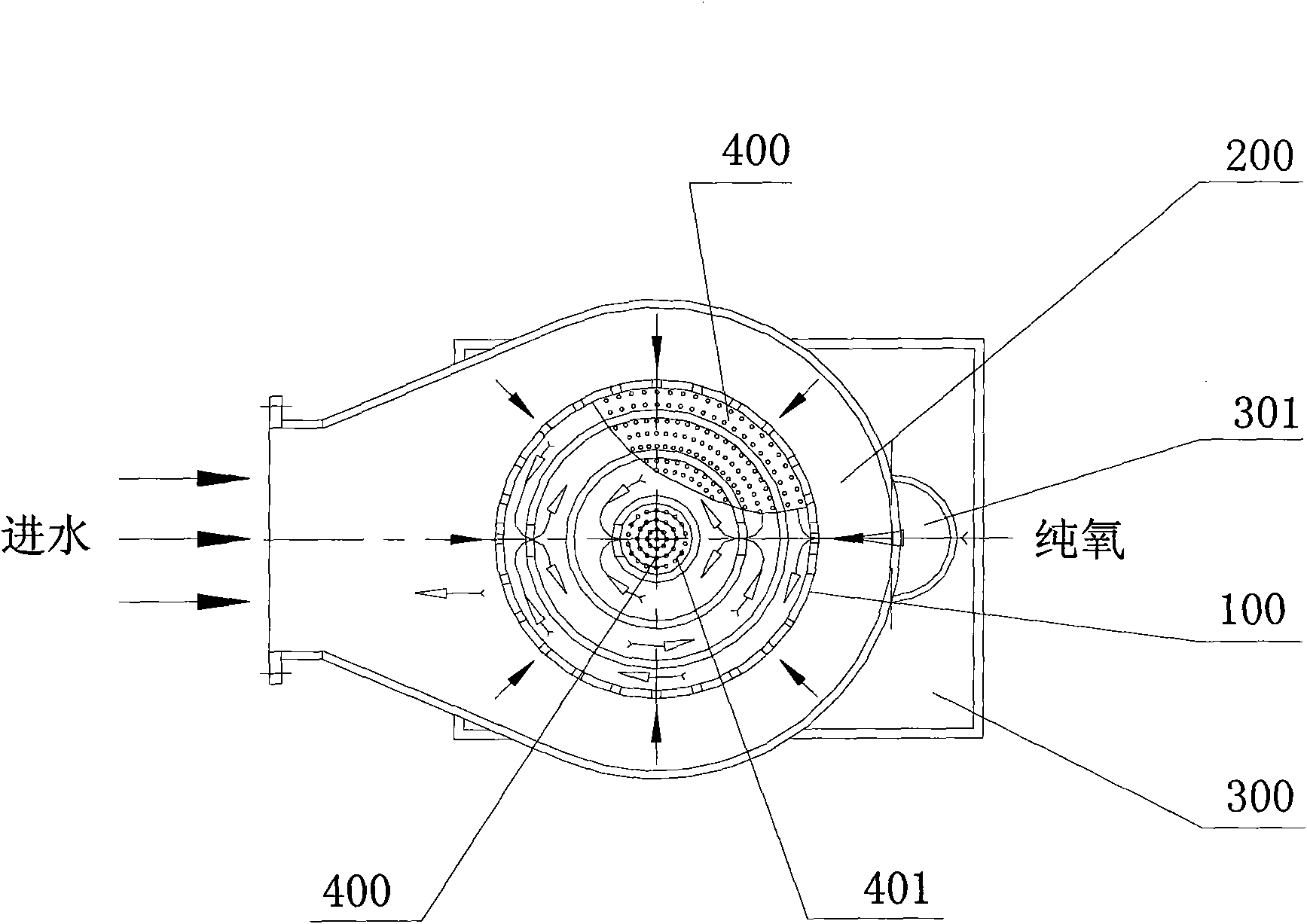
[0023] Such as figure 1 , figure 2 As shown, the trickle-type pure oxygen dissolved oxygen device of the present invention includes a group of mixing chambers 100, a water distribution tank 200 and a water outlet tank 300; the water distribution tank 200 is arranged above the mixing chamber 100, and the water outlet tank 300 is arranged on the mixing chamber Below the chamber 100 , a drain pipe 301 with a water level maintaining function is provided in the outlet tank 300 . In this embodiment, the mixing chamber 100 is a group of annular chambers.

[0024] The mixing chamber 100 is composed of several cavities 101 whose diameter gradually decreases from the outside to the inside. Generally, the number of cavities 101 is 3 to 5, and the air inlet pipe 102 is arranged between the cavities 101 from the outside to the inside. Connected to each other, oxygen enters the mixing chamber 100 through the intake pipe 102, so that pure oxygen gradually enters the inner chamber 101 from ...


PUM

PropertyMeasurementUnit
pore sizeaaaaaaaaaa
porosityaaaaaaaaaa

Abstract

The invention provides a trickle type pure oxygen dissolving device. The device comprises a group of annular mixed cavity, a water distribution channel and a water outlet channel, wherein the mixed cavities consists of a plurality of cavities which are mutually sheathed and the diameters of the cavities gradually reduce from outside to inside; the cavities are communicated mutually from outside toinside by arranging a water inlet pipe; oxygen enters the mixed cavity through a gas inlet pipe to ensure the oxygen concentrations of all cavities to be consistent basically; the water outlet channel is internally provided with a water discharge pipe with the water level retaining function; a water body forms a uniform water flow through a water distribution plate in the water distribution channel to enter the mixed cavity; the oxygen sequentially enters every cavity in the mixed cavity from outside to inside through the gas inlet pipe arranged on the mixed cavities and conducts gas-liquid exchange with the water body to realize oxygenation of the water body; and the residual oxygen that is not completely dissolved in water through the cavities enters a tail gas recovery pipe to be mixedwith the water flow overflowing in the tail gas recovery pipe, so as to improve the utilization rate of oxygen to the greatest extent. The oxygenated water body is discharged by the water discharge pipe through the water outlet channel.

Description

technical field [0001] The invention relates to an oxygen dissolving device for increasing oxygen in a water body, in particular to a trickle-type pure oxygen dissolving device which uses pure oxygen as an oxygen source to increase oxygen in a water body. Background technique [0002] With the rapid development of my country's aquaculture recirculating aquaculture industry, as a key technical link in the aquaculture system, water body aeration technology has been paid more and more attention. According to different oxygen sources, the oxygenation of the water body in the aquaculture system can be divided into two ways: blast aeration and pure oxygen oxygenation. Release devices (such as aeration heads, aeration tubes and aerators, etc.) release air into the water body in the form of tiny bubbles to achieve gas-liquid exchange with the water body and achieve the purpose of increasing oxygen in the water body in the aquaculture system. [0003] The oxygen source of the pure o...

Claims


Application Information

Patent Timeline
Patent Type & Authority Applications(China)
IPC IPC(8): C02F7/00
CPCY02W10/10
Inventor 倪琦张宇雷管崇武宋虹桥
Owner FISHERY MACHINERY & INSTR RES INST CHINESE ACADEMY OF FISHERY SCI
Learn More