Minitype single-chip LCOS projection optical engine

A projection optical machine and single-chip technology, applied in the field of optical instruments, can solve the problems of reducing the heat of the system and the reliability of the whole machine, reducing the energy utilization efficiency of the light source, and lack of shaping measures for the lighting beam, so as to improve the image clarity , weight reduction, and simple manufacturing process

Inactive Publication Date: 2010-03-10
南阳市海科光电有限责任公司
View PDF0 Cites 13 Cited by
  • Summary
  • Abstract
  • Description
  • Claims
  • Application Information

AI Technical Summary

Problems solved by technology

In addition, since the aspect ratio of the current LCOS chip is 4:3 or 16:9, in order to effectively use the energy of the light source, there is a problem of shaping the illumination beam. Some manufacturers develop micro-projectors out of cost considerations. , the lack of shaping measures for the illumination beam, which reduces the utilization efficiency of the light source energy to a certain extent
For the projection lens of the main part of the light engine, in order to maintain a certain range of high-quality imaging, generally 6-8 glass lenses will be used, which will also bring a certain cost pressure to the micro projection light engine, limited by the etendue, The relative aperture of the projection optical lens cannot be greater than 2.4, so the design of the projection lens is very important
[0004] The technical problems faced by the micro optical engine in the future development mainly include the low light output of the system, how to reduce the heat of the system and the reliability of the whole machine within a limited range, which is also the bottleneck problem restricting the development of the micro optical engine

Method used


Image

  • Minitype single-chip LCOS projection optical engine
  • Minitype single-chip LCOS projection optical engine
  • Minitype single-chip LCOS projection optical engine

Examples


Embodiment Construction

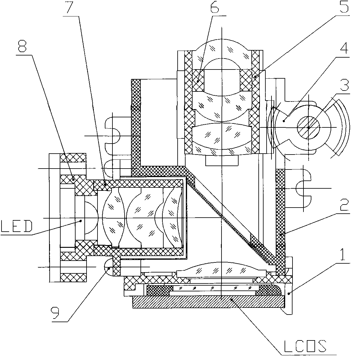
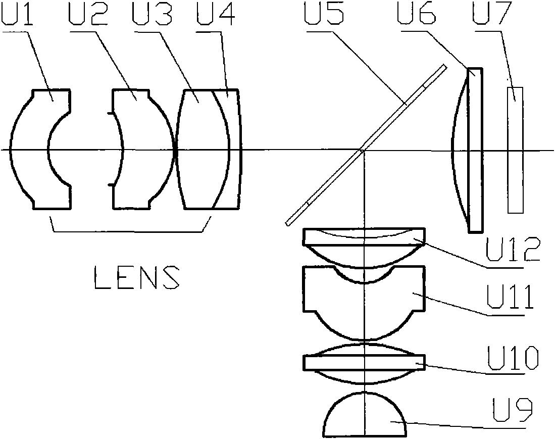
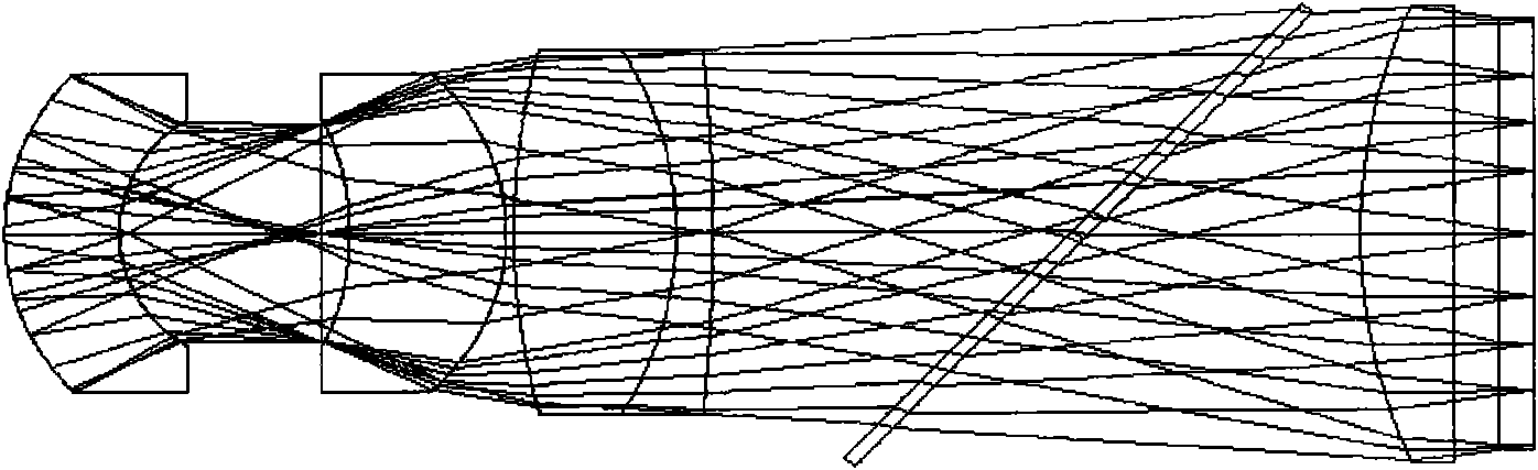
[0023] Such as figure 1 , 2The shown miniature single-chip LCOS projection optical machine is composed of an illumination system, a PBS beam splitter, a field lens, an LCOS chip and a projection lens. The lighting system is arranged on the lighting seat 7, and the projection lens [LENS], PBS beam splitter [U5], field mirror [U6] and LCOS chip [U7] are arranged along the imaging optical axis of the system from the screen side to the image plane side in order Arrangement; PBS beam splitter [U5] forms an included angle of 45 degrees with the imaging optical axis; the lighting system consists of LED light source, lens [U9], first condenser lens [U10], cylindrical lens [U11], second condenser lens [U12] ] are arranged sequentially along the optical axis of the lighting system. The optical axis of the lighting system is 90 degrees to the optical axis of the imaging optical path. The bending direction of the cylindrical lens [U11] is consistent with the direction of the lighting bea...


PUM


Abstract

The invention relates to a minitype single-chip LCOS projection optical engine which is composed of a projection lens, a PBS beam splitter, a field lens and an LCOS chip which are sequentially arrayedalong a system imaging optical axis from a screen side to an image plane side, the PBS beam splitter and the imaging optical axis form a 45-degree angle, and an illuminating system of an optical engine is formed by an LED light source lens, a first condenser lens, a cylindrical lens and a second condenser lens which are sequentially arrayed along the optical axis of the illuminating system. The optical axis of the illuminating system and the optical axis of an imaging optical path from a 90-degree angle, and the PBS beam splitter, the field lens and the LCOS chip are commonly used by the imaging optical path and an illuminating optical path. An illuminating central beam is vertically radiated on the LCOS chip after being reflected by the PBS beam splitter, the system moves forward and backward to realize focusing along the imaging optical path by the projection lens, so as to ensure to realize to image clearly at different distances. The system has low cost and good process and is suitable for batch production.

Description

technical field [0001] The invention belongs to the technical field of optical instruments, and in particular relates to a miniature single-chip LCOS projection optical machine suitable for being built into products such as mobile phones, digital cameras, and handheld projectors. Background technique [0002] With the rapid development of LED light source technology in recent years, the trend of its use in micro-projectors is very obvious and the potential is huge, so that there will be explosive market demand for micro-optical projectors in the next few years. In recent years, Texas Instruments has developed 0.17” and 0.2” DMD microchips specifically for the field of micro projection. However, due to the high cost of DMDs, it is difficult to bring micro projection optical engines into the market on a large scale in a short period of time. At present, the 0.38” and 0.44” single-chip micro-LCOS chips developed by some LCOS chip manufacturers in Taiwan, such as Lijing Company,...

Claims


Application Information

Patent Timeline
Patent Type & Authority Applications(China)
IPC IPC(8): G03B21/14G03B21/20G02B13/00G02B13/18G02B1/04
Inventor 许东升
Owner 南阳市海科光电有限责任公司
Why Eureka
Try Eureka