Rotor structure of switched reluctance motor for reducing vibration and noise

A technology of switched reluctance motor and rotor structure, applied in the direction of magnetic circuit shape/style/structure, magnetic circuit rotating parts, etc. Torque fluctuation and other problems, to achieve the effect of smooth torque, reduce severe vibration, and reduce large fluctuations

Inactive Publication Date: 2010-03-10
HEBEI UNIV OF TECH
View PDF0 Cites 9 Cited by
  • Summary
  • Abstract
  • Description
  • Claims
  • Application Information

AI Technical Summary

Problems solved by technology

However, compared with other traditional motors, switched reluctance motors have greater noise. The double-saliency structure of the stator and rotor and the switching power supply make the switched reluctance motor drive system a highly coupled multi-variable and extremely nonlinear system. system, the torque ripple during operation is very obvious, so it causes motor noise and torque fluctuation, which directly affects the application of switched reluctance motors in occasions with high requirements for running quality
Many scholars at home and abroad have done a lot of research on how to reduce the noise of switched reluctance motors. Most of the noise suppression of switched reluctance motors is carried out in the field of control strategies, such as stator vibration of switched reluctance motors. In terms of characteristic analysis, noise estimation, and active noise reduction control strategies, there are few studies on the structural form of switched reluctance motors.

Method used


Image

  • Rotor structure of switched reluctance motor for reducing vibration and noise
  • Rotor structure of switched reluctance motor for reducing vibration and noise
  • Rotor structure of switched reluctance motor for reducing vibration and noise

Examples


Embodiment Construction

[0018] The present invention is specifically described as follows in conjunction with accompanying drawing:

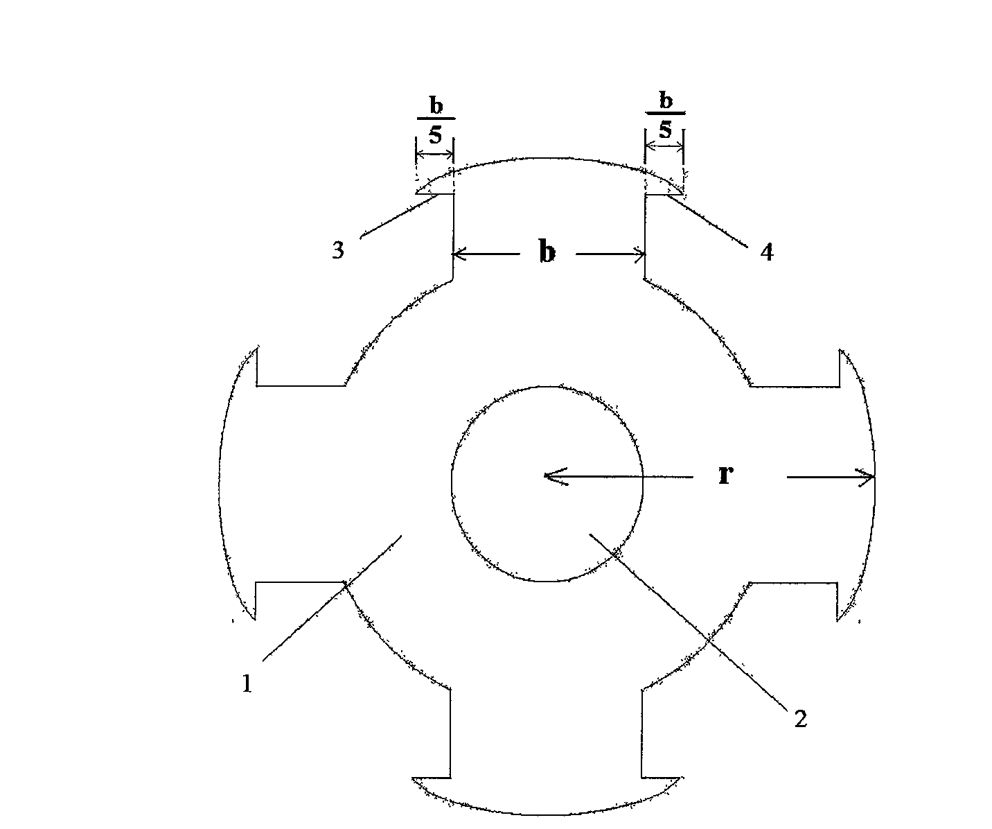
[0019] The rotor of the switched reluctance motor provided by the present invention is made of laminated silicon steel sheets, and the pole-shaped end of the rotor is a salient pole structure with arc-shaped pole tips. The rotor salient pole structure is as follows: each rotor salient pole ends with an arc-shaped pole tip extending left and right along the outer diameter of the rotor.

[0020] The left and right arc-shaped pole tips extending along the outer diameter of the rotor are symmetrical; the horizontal length of the arc-shaped pole tips is 1 / 5 of the rotor pole width; the rotor salient pole structure is mainly suitable for three-phase 6 / 4-pole, three-phase 6 / 8-pole switched reluctance motor, four-phase 8 / 6-pole switched reluctance motor.

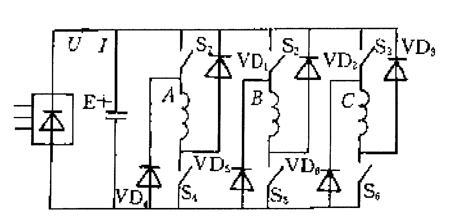
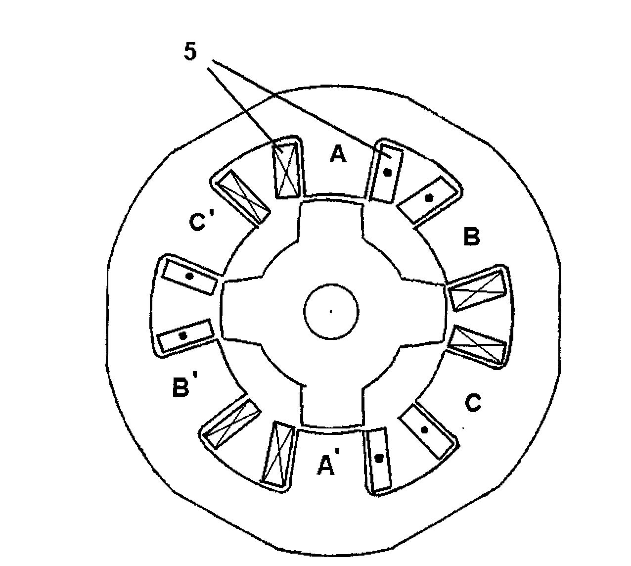
[0021] Taking a three-phase 6 / 4-pole switched reluctance motor as an example for illustration, the three-phase 6 / 4-pole ...


PUM


Abstract

The invention relates to a rotor structure of a switched reluctance motor for reducing vibration and noise. The rotor structure is formed by stacking silicon steel sheets, and a salient pole structurewith a an arc-shaped pole tip is arranged at the tail end of a rotor pole, wherein the structure of rotor salient pole is that an arc-shaped pole tip extends left and right along the circumference ofthe rotor outer diameter at the tail end of each rotor salient pole. The invention can reduce great sudden change of radial force which is caused when a rotor edge and a stator pole edge are superposed in the rotation process of the motor rotor, reduces the compression and expansion vibration of a motor housing structure caused by sudden change of the radial magnetic attraction, reduce the torquefluctuation which is caused when the motor rotor edge and the stator pole edge are superposed during rotation and reduce the torque pulsation.

Description

Technical field: [0001] The invention relates to a switched reluctance motor, in particular to a vibration-reducing and noise-reducing rotor structure of the switched reluctance motor. technical background [0002] The switched reluctance motor speed control system is an AC speed control system integrating switched reluctance motor, modern power electronics and control technology. It has a series of advantages: simple structure, strong, low manufacturing cost, small maintenance, wide speed range, high efficiency, etc., making it a very potential member of the variable speed drive system. Since the 1990s, switched reluctance speed control systems have been more and more used in the drive systems of electric vehicles, mines, oil fields, textile machinery and other industrial parts. In particular, its good high-speed performance and strong fault tolerance make it widely used in aerospace, high-speed centrifuges and other fields with harsh environments and high safety requireme...

Claims


Application Information

Patent Timeline
Patent Type & Authority Applications(China)
IPC IPC(8): H02K1/24
Inventor 孙鹤旭李洁郑易何林米彦青贾婧
Owner HEBEI UNIV OF TECH
Why Eureka
Try Eureka