
Rotor structure of switched reluctance motor

A technology of switched reluctance motor and rotor structure, applied in the direction of magnetic circuit shape/style/structure, magnetic circuit rotating parts, etc., can solve the problem of reducing the radial force of the rotor slot, weakening the effect of radial force, increasing motor loss, and large use limitations, etc. problems, to achieve the effect of alleviating large torque fluctuations, reducing noise, and maintaining the output torque capability

Inactive Publication Date: 2010-03-10
HEBEI UNIV OF TECH
View PDF0 Cites 6 Cited by
  • Summary
  • Abstract
  • Description
  • Claims
  • Application Information

AI Technical Summary

Problems solved by technology

The optimization scheme proposed in this document can effectively reduce vibration, but its use is limited, and it is only suitable for switched reluctance motors running in a single direction. If the running direction of the motor changes, the effect of reducing the radial force of the rotor slots is weakened, and The presence of rotor slots increases wind resistance, increases motor losses, and reduces system efficiency

Method used


Image

  • Rotor structure of switched reluctance motor
  • Rotor structure of switched reluctance motor
  • Rotor structure of switched reluctance motor

Examples


Embodiment Construction

[0022] The present invention is specifically described as follows in conjunction with the accompanying drawings:

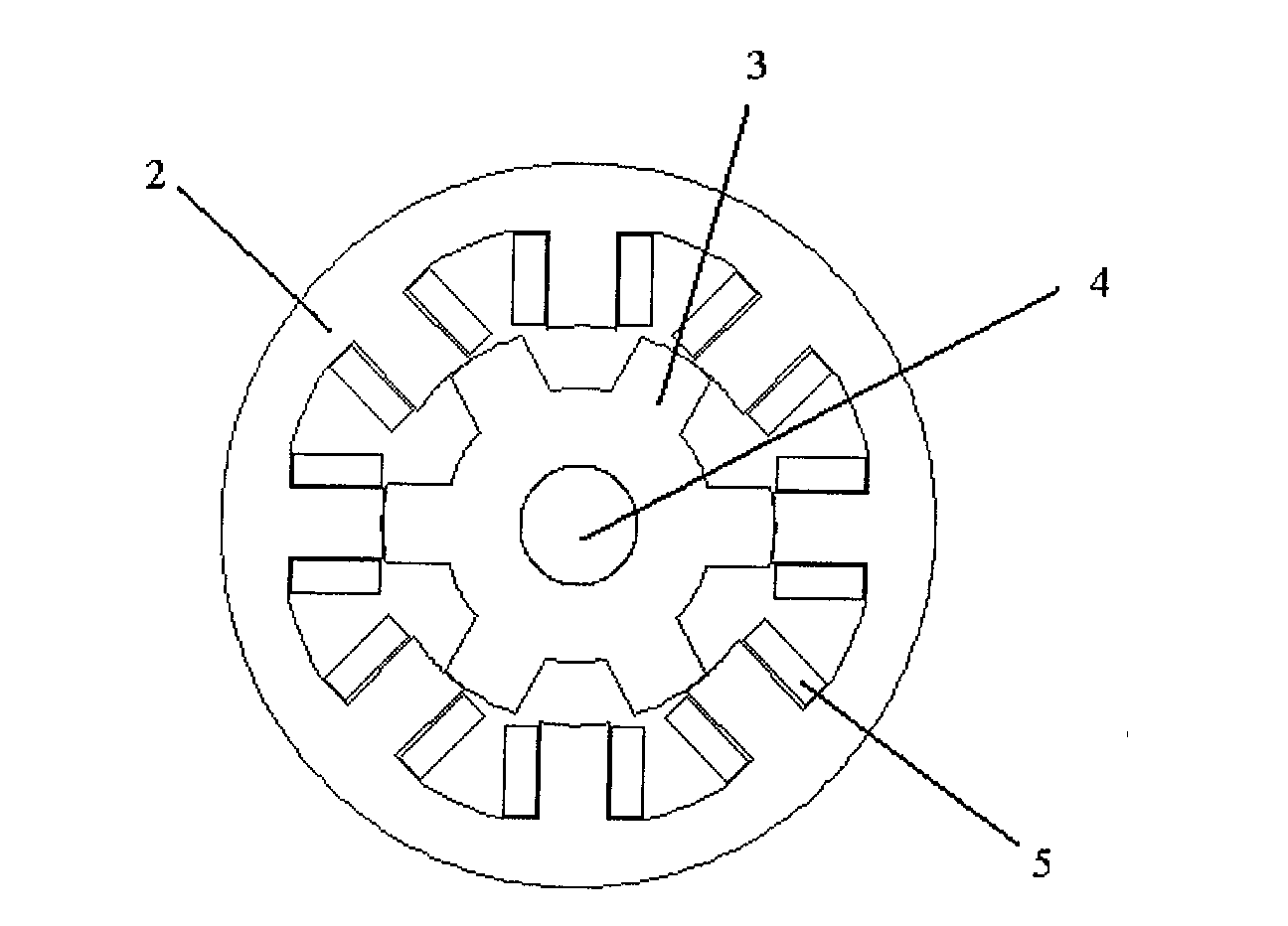
[0023] The rotor of the switched reluctance motor provided by the invention has no windings and no permanent magnets, and is formed by laminating silicon steel sheets, and the rotor pole type is a multi-air gap salient pole structure that reduces vibration and noise. The rotor structure is as follows: the protrusion at the end of the rotor is a multi-air-gap stepped type.

[0024] The left and right steps of the multi-air gap stepped type are symmetrical. The widths of the left and right edges of the multi-air-gap stepped shape each account for 1 / 6 of the rotor pole width. The protruding height of the end of the multi-air gap stepped rotor is 1 / 6 of the overall height of the rotor pole. The multi-air-gap stepped type has two layers of steps, and the height and width of each layer of steps are equal.

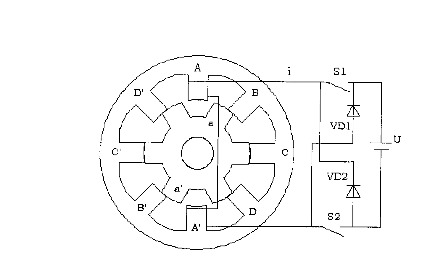
[0025] Taking a four-phase 8 / 6-pole switched reluctance moto...


PUM


Abstract

The invention relates to a rotor structure of a switched reluctance motor, which is formed by stacking silicon steel sheets and has no windings or permanent magnets. The polar form of the rotor is a multi-air-gap salient pole structure for reducing vibration and noise, and the salient pole at the tail end of the rotor is of a multi-air-gap step type. The invention can realize steady conversion oftorques during the operation of motors, effectively reduces the great fluctuation of the torque caused by sudden change of the torque in the operation process of motors and reduces compression and expansion vibration of a motor housing structure caused by rapid alternation of the radial magnetic attraction of the motor so as to achieve the effect of reducing the vibration noise of the motor. The invention can maintain a certain output capacity of the motor and is suitable for all occasions where the switched reluctance motor is applied.

Description

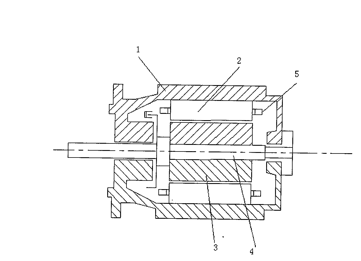
Technical field: [0001] The invention relates to a switched reluctance motor, in particular to a rotor structure of the switched reluctance motor. technical background [0002] Switched reluctance motor has simple structure, superior performance and high reliability. It covers various high and low speed drive speed regulation systems ranging from 10W to 5MW, and can be widely used in various occasions where speed regulation and high efficiency are required. [0003] The general switched reluctance motor structure is as follows figure 1 As shown, a stator 2, a rotor 3, and a motor shaft 4 are arranged inside the motor casing 1, and the stator 2 and the rotor 3 are formed by laminating silicon steel sheets. The rotor 3 has no windings and no permanent magnets, the stator 2 is on the periphery of the rotor 3, the windings 5 ​​are wound on the stator 2 in a concentrated manner, and the windings of radially opposite poles are connected in series to form a group. The commonly us...

Claims


Application Information

Patent Timeline
Patent Type & Authority Applications(China)
IPC IPC(8): H02K1/26
Inventor 孙鹤旭李洁雷兆明何林高洁
Owner HEBEI UNIV OF TECH
Learn More