Excitation system of generator

An excitation system and generator technology, applied in the field of generator excitation, can solve the problems of inconvenient operation and maintenance of the unit, low knowledge and complexity of operation and maintenance personnel, and achieve the elimination of hidden dangers of system de-excitation failure and simple system structure , The effect of reducing the maintenance workload

Inactive Publication Date: 2010-03-10
WUHAN WUDA ELECTRIC POWER TECH
View PDF0 Cites 12 Cited by
  • Summary
  • Abstract
  • Description
  • Claims
  • Application Information

AI Technical Summary

Problems solved by technology

[0004] For small generator sets, because the excitation system is more complex, and the mechanical part of the de-excitation switch will fail due to wear and tear, it will bring inconvenience to the operation and maintenance of the unit, especially for small hydropower stations, the knowledge of operation and maintenance personnel is generally not high

Method used


Image

  • Excitation system of generator
  • Excitation system of generator
  • Excitation system of generator

Examples


Embodiment Construction

[0019] The present invention will be further described below in conjunction with the accompanying drawings.

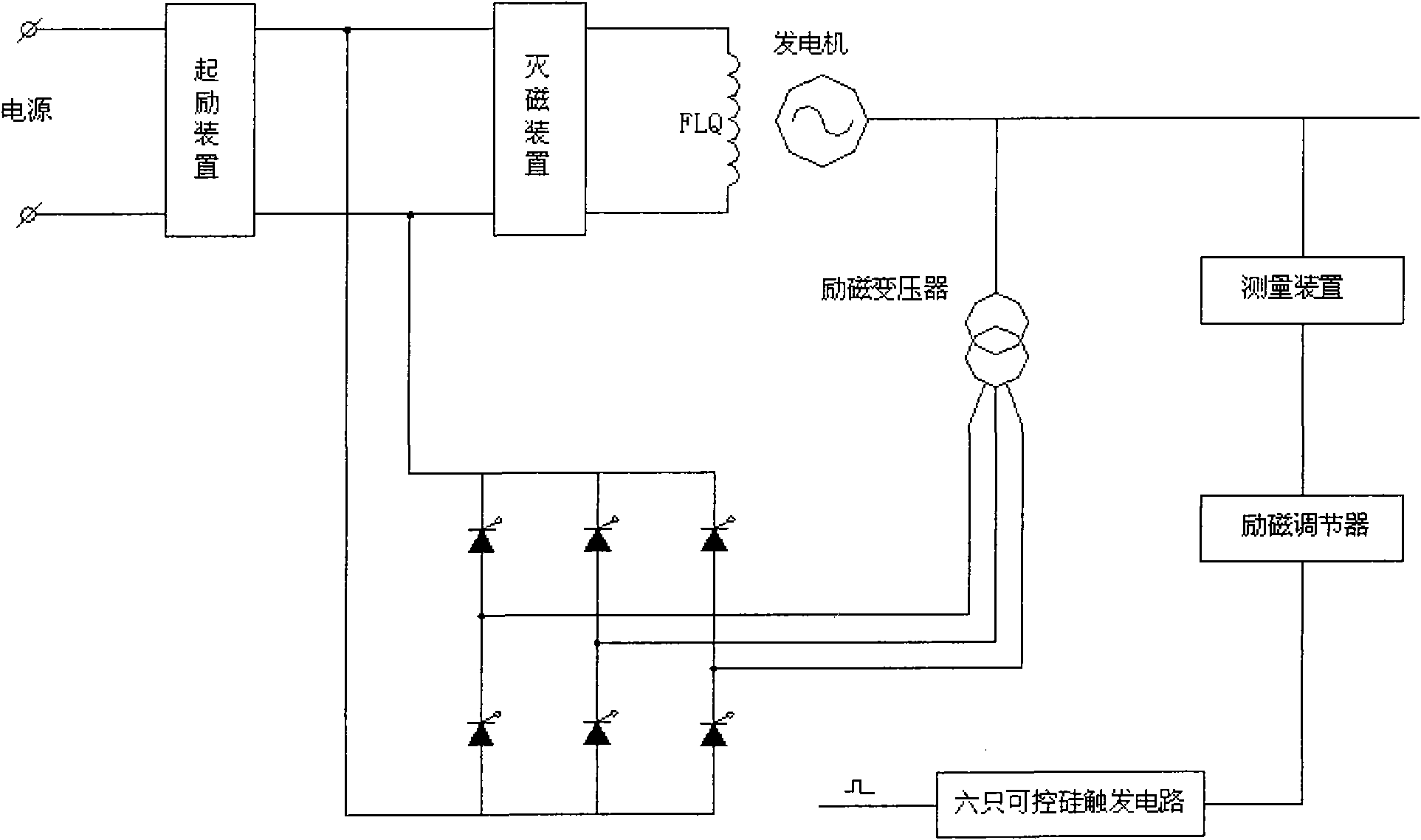
[0020] Such as figure 1 Shown is the traditional static excitation system, which includes excitation transformer, excitation regulator, thyristor rectifier bridge, de-excitation device, measuring device, thyristor trigger circuit, excitation winding FLQ, etc., among which the thyristor rectifier is all composed of thyristor silicon controlled composition.

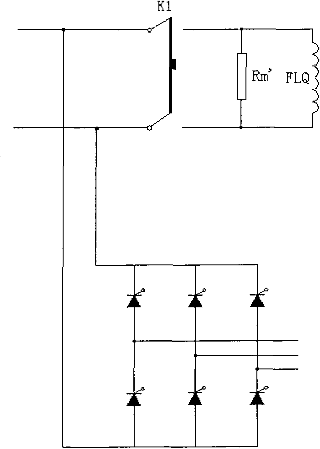
[0021] Such as figure 2 Shown is the circuit connection diagram of the de-excitation device in the traditional static excitation system. The traditional de-excitation method is to turn off the switch K1, separate the rectifier bridge from the excitation winding FLQ, and make the excitation winding FLQ and the de-excitation resistor Rm' form a loop to achieve the purpose of de-excitation.

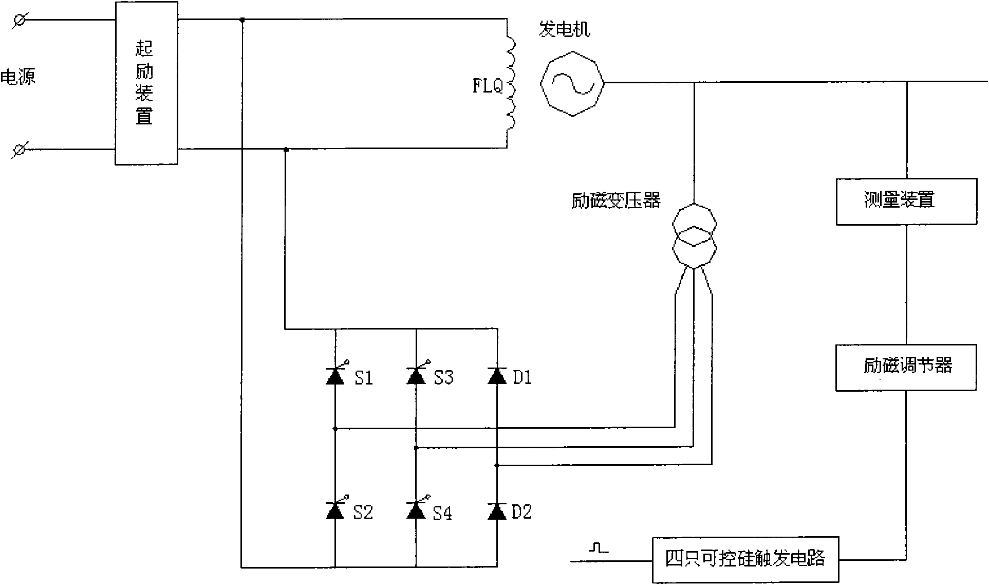
[0022] And the present invention provides a kind of new generator static excitation system technical scheme, such as image...


PUM


Abstract

An excitation system of a generator comprises an excitation device, an excitation winding, an excitation transformer, a rectifier bridge which is connected with the secondary edge of the excitation transformer, an excitation regulator and a silicon-controlled trigger circuit; the rectifier bridge comprises a silicon-controlled rectifier and diodes; one bridge arm of the rectifier bridge is connected with two diodes and the other bridge arms are connected with the silicon-controlled rectifier; and the output end of the rectifier bridge is connected with the excitation winding of the generator.The excitation system of the generator replaces two silicon-controlled rectifiers on one bridge arm of the rectifier bridge in the traditional excitation system with dioxides, therefore, not only thecontrollability and the output value of the rectifier bridge are not influenced on the condition of rectification when in normal work, but also can the dioxides form a loop with the excitation windingso as to achieve the de-excitation function when de-excitation is required, thereby eliminating the de-excitation device in the traditional excitation system, simplifying the system loop, and improving the reliability of the excitation system.

Description

technical field [0001] The invention relates to generator excitation technology, in particular to a generator excitation system suitable for small generators. Background technique [0002] At present, domestic generators mostly adopt static excitation mode. The traditional static excitation system is composed of excitation transformer, excitation regulator, silicon controlled rectifier bridge, de-excitation device, measuring device and other parts. Each part plays a different role in the excitation system. The function of the de-excitation device is to quickly consume the energy in the rotor of the generator when the generator needs to be de-excited for some reason, so as to achieve the purpose of de-excitation. [0003] The degaussing device is mainly composed of a degaussing switch and a degaussing resistor. There are many types of degaussing switches, and there are several types of degaussing resistors, such as nonlinear resistance and linear resistance, but the principl...

Claims


Application Information

Patent Timeline
Patent Type & Authority Applications(China)
IPC IPC(8): H02P9/26H02H7/06
Inventor 江忠旭
Owner WUHAN WUDA ELECTRIC POWER TECH
Why Eureka
Try Eureka