Method for inhibiting electromagnetic interference and electromagnetic interference filter

An electromagnetic interference and filter technology, applied in the electronic field, can solve problems such as complex circuits and increased costs, and achieve the effect of simplifying circuits and saving costs

Active Publication Date: 2010-03-10
HUAWEI DEVICE CO LTD
View PDF0 Cites 1 Cited by
  • Summary
  • Abstract
  • Description
  • Claims
  • Application Information

AI Technical Summary

Problems solved by technology

Using multiple EMI devices in series can achieve the purpose of suppressing electromagnetic interference at multiple frequency points, but using multiple EMI devices will lead to complex circuits and increased costs

Method used


Image

  • Method for inhibiting electromagnetic interference and electromagnetic interference filter
  • Method for inhibiting electromagnetic interference and electromagnetic interference filter
  • Method for inhibiting electromagnetic interference and electromagnetic interference filter

Examples


Embodiment 1

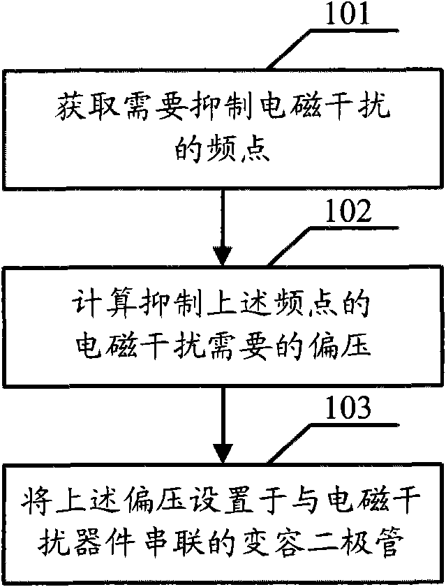
[0023] Embodiment 1, the embodiment of the present invention provides a method for suppressing electromagnetic interference, including:

[0024] 101: Obtain the frequency points that need to suppress electromagnetic interference;

[0025] 102: Calculate the bias voltage required to suppress the electromagnetic interference at the above frequency point;

[0026] The above calculation of the bias voltage required to suppress the electromagnetic interference at the above frequency point includes: calculating the junction capacitance required to suppress the electromagnetic interference at the above frequency point; and calculating the bias voltage required for the varactor diode to provide the above junction capacitance.

[0027] 103: Set the above-mentioned bias voltage on a varactor diode connected in series with the electromagnetic interference device; one end of the above-mentioned varactor diode is connected to the above-mentioned electromagnetic interference device, and the...

Embodiment 2

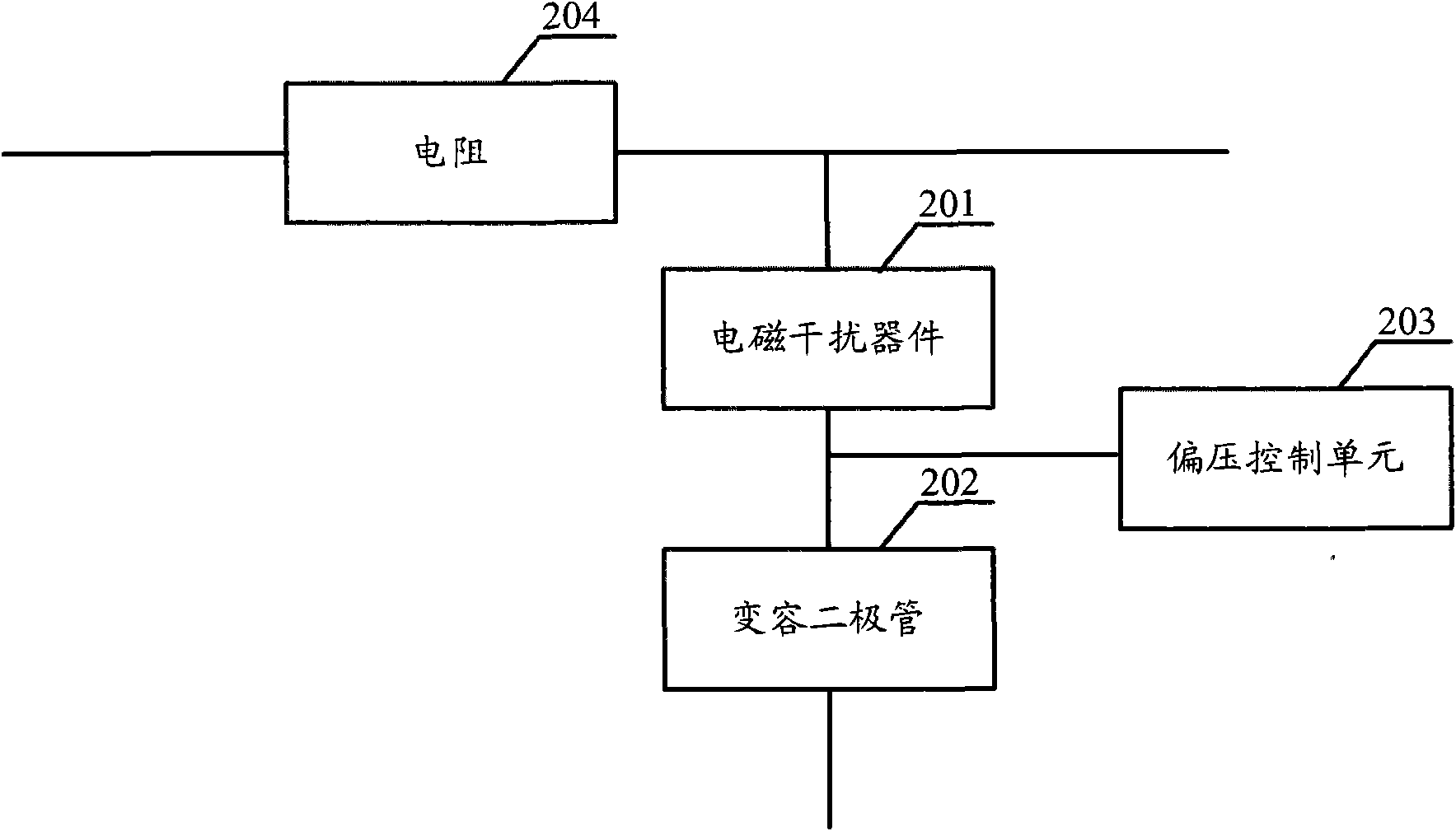
[0035] Embodiment two, such as figure 2 As shown, the embodiment of the present invention also provides an electromagnetic interference filter, including:

[0036] A variable capacitance diode 202 connected in series with the electromagnetic interference device 201, one end of the above-mentioned variable capacitance diode 202 is connected to the above-mentioned electromagnetic interference device 201, and the other end is grounded;

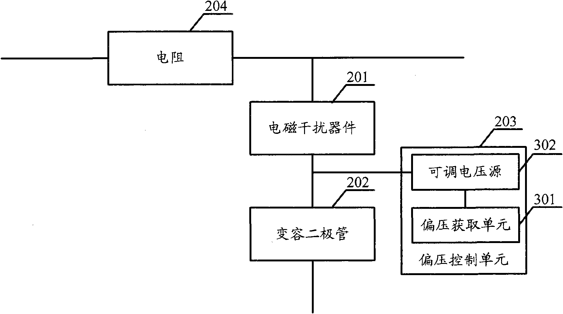
[0037] A bias voltage control unit 203 is connected in parallel with the varactor diode 202, and the bias voltage control unit 203 is used to provide a bias voltage for the varactor diode 202;

[0038] One end of the electromagnetic interference device 201 of the above-mentioned EMI filter is connected to a resistor 204, and the other end is connected to a varactor diode 202;

[0039] refer to figure 2 , the signal that needs to use the EMI filter is input from one end of the above-mentioned resistor 204, passes through the resistor 204, and ...

Embodiment 3

[0050] Embodiment three, such as Figure 5 As shown, it is a schematic structural diagram of the EMI filter provided by the embodiment of the present invention. This structure can have many paths in the EMI filter to deal with the EMI in multiple lines in the device. Generally, there are 2 paths, 8 channels, 32 channels, etc., the specific number of channels does not affect the implementation of the embodiment of the present invention, and is not limited in this embodiment of the present invention. In the embodiment of the present invention, the varactor diode adopts a structure in which a diode D1 with a positive temperature coefficient and a diode D2 with a negative temperature coefficient are connected in parallel, and the EMI device takes a capacitor C1 as an example, and the capacitor C1 is connected to one end of the resistor R. A bias voltage is set at the middle connection part where the capacitor C1 is connected to the varactor diode, and the bias voltage can be set m...


PUM


Abstract

The embodiment of the invention discloses a method for inhibiting EMI and an EMI filter. The realization of the method comprises the following steps: obtaining the frequency points needing to inhibit the EMI, calculating the biasing voltage required by the EMI of the frequency points, arranging the biasing voltage at a variable capacitance diode connected in series with the EMI device (one end ofthe variable capacitance diode is connected with the EMI device and the other end thereof is grounded.), and utilizing the EMI device and the variable capacitance diode to inhibit the EMI of the frequency points. By increasing the variable capacitance diodes connected in series with the EMI device and changing the biasing voltage of the variable capacitance diodes, the EMI filter can work at different working frequencies so that the working frequency of the EMI filter is adjustable and the purpose of inhibiting the EMI at multiple frequency points can be realized. With realizing the purpose of inhibiting the EMI of multiple frequency points, the circuit is simplified and the cost is saved.

Description

technical field [0001] The invention relates to the field of electronic technology, in particular to a method for suppressing electromagnetic interference and an electromagnetic interference filter. Background technique [0002] Electromagnetic interference (EMI) devices are widely used in various electromagnetic products to suppress EMI generated by circuit modules. There are many types of electromagnetic products, such as: inductors, capacitors, exclusion, displacement and so on. [0003] The EMI filter includes: a resistor and an EMI device; one end of the EMI device is connected to the above resistor, and the other end is grounded. In the above-mentioned devices for suppressing electromagnetic interference, since the operating frequency of the EMI device is fixed, it can only suppress the electromagnetic interference at the frequency corresponding to the above-mentioned operating frequency. [0004] In many occasions, a signal channel may generate electromagnetic inter...

Claims


Application Information

Patent Timeline
IPC IPC(8): H03H11/04H03H7/01
Inventor 狄伟温剑锋徐广义
Owner HUAWEI DEVICE CO LTD
Why Eureka
Try Eureka